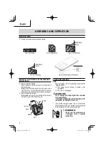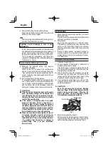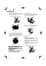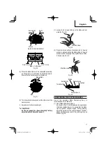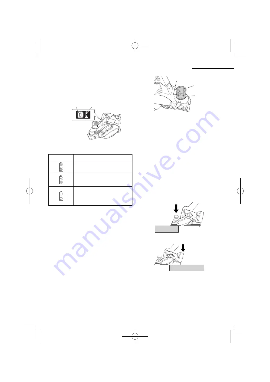
Knob
Scale
Triangular mark
Fig. 9
4. Surface cutting
Rough cutting should be accomplished at large
cutting depth and at a suitable speed so that shavings
are smoothly ejected from the machine. To ensure
a smoothly
fi
nished surface,
fi
nish cutting should
be accomplished at small cutting depth and at low
speed.
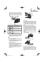
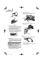
5. Beginning and ending the cutting operation
As shown in Fig. 10, place the front base of the planer
on the workpiece and support the planer horizontally.
Turn ON the power switch, and slowly operate the
planer toward the leading edge of the workpiece.
Firmly depress the front half of the planer at the
fi
rst
stage of cutting and, as shown in Fig. 11, depress
the rear half of the planer at the end of the cuning
operation.
The planer must always be kept
fl
at throughout the
entire cutting operation.
Fig. 10 Beginning of cutting operation
Fig. 11 End of cutting operation
6. Precaution after
fi
nishing the planing operation
When the planer is suspended with one hand after
fi
nishing the planing operation, ensure that the cutting
blades (base) of the planer do not contact or come too
near your body. Failure to do so could result in serious
injury.
When releasing your
fi
nger from the remaining battery
indicator switch, the remaining battery indicator lamp
goes o
ff
. The Table 5 shows the state of remaining
battery indicator lamp and the battery remaining
power.
Remaining battery
indicator switch
Remaining battery
indicator lamp
Fig. 8
Table 5
State of lamp
Battery Remaining Power
The battery remaining power is
enough.
The battery remaining power is a half.
The battery remaining power is nearly
empty.
Re-charge the battery soonest
possible.
As the remaining battery indicator shows somewhat
di
ff
erently depending on ambient temperature and
battery characteristics, read it as a reference.
NOTE
○
Do not give a strong shock to the switch panel or
break it. It may lead to a trouble.
○
To save the battery power consumption, the
remaining battery indicator lamp lights while pressing
the remaining battery indicator switch.
3. Adjusting the cutter depth
Turn the knob in the direction indicated by the arrow in
Fig. 9 (clockwise), until the triangular mark is aligned
with the desired cutting depth on the scale.
An interval between graduations on the scale
corresponds to 1/256"(0.1mm) in cutting depth. The
cutting depth can be adjusted within a range of 0
―
5/64"(0
―
2.0 mm).
13
English
000Book̲P18DSL.indb 13
000Book̲P18DSL.indb 13
2018/10/16 17:38:41
2018/10/16 17:38:41
Summary of Contents for P 18DSL
Page 65: ...65 000Book P18DSL indb 65 000Book P18DSL indb 65 2018 10 16 17 38 46 2018 10 16 17 38 46 ...
Page 66: ...66 000Book P18DSL indb 66 000Book P18DSL indb 66 2018 10 16 17 38 46 2018 10 16 17 38 46 ...
Page 67: ...67 000Book P18DSL indb 67 000Book P18DSL indb 67 2018 10 16 17 38 46 2018 10 16 17 38 46 ...


