– 13 –
English
To reduce the risk of serious personal injury, turn off
and disconnect the miter saw from power source outlet
before installing and removing mounting brackets,
making adjustment or doing repairs. An unintentional
start-up can cause injury.
ADJUSTMENT INSTRUCTIONS
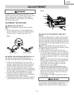
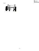
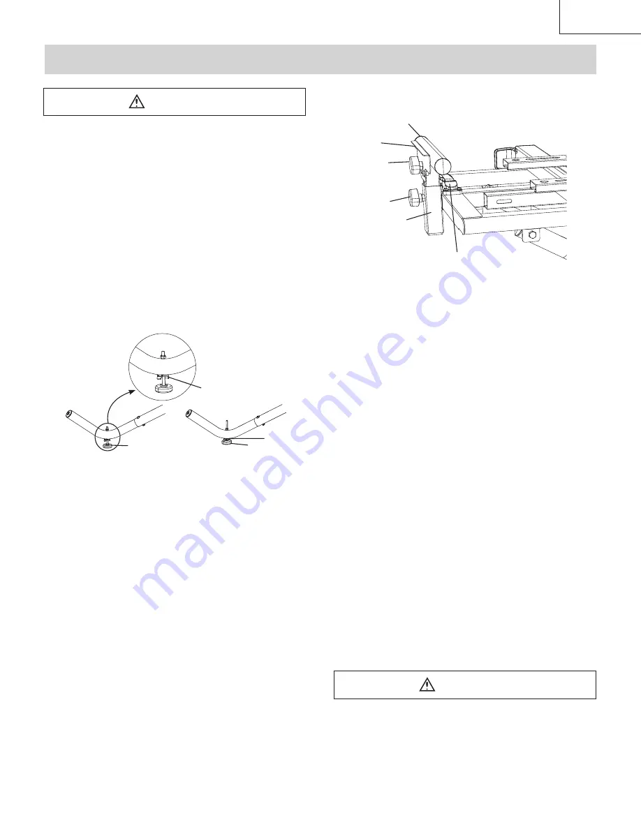
ADJUSTING FOOT PAD (FIG. P)
NOTE:
The adjustable foot pad is used to level the
stand.
1. Loosen the wing nut (1), turn the adjustable foot
pad (2) clockwise to raise and counterclockwise to
lower the stand, then tighten the wing nut (1).
Fig. P
ADJUSTING THE EXTENSION SUPPORTS (FIG. Q)
The extension support assembly helps keep the
workpiece level and stable during cutting operations.
1. Lift the cam locking handle (1) up to loosen the
extension support and slide the extension arm (2) to
the desired length. Press down on the cam locking
handle (1) to lock the extension support in place.
2. Loosen the height adjustment knob (3) to adjust the
extension support assembly (4) to the desired height
and then tighten the height adjustment knob (3).
3. If repetitive cutting is required, loosen the plate
adjustment knob (5) to adjust the work stop plate (6)
to the desired height, and then tighten.
4. The adjustment steps for other side of the extension
support assembly is the same as the above steps.
Fig. Q
ADJUSTING THE SAW MOUNTING BRACKETS
(FIG. R)
If the saw mounting brackets can slide over the top rails
or be removed from the top rails when the bracket cam
latches (1) are locked, the bracket adjustment screws (2)
need to be tightened. If the saw mounting brackets do not
fit over the top rails, the bracket adjustment screws need
to be loosened.
NOTE:
The miter saw should be removed from the
mounting brackets before attempting to tighten or loosen
the bracket adjustment screws (2).
1. Loosen the lock nut (3) using a 10 mm wrench.
2. Go through the hole (4) of the power cord clamp (5)
by using a Phillips screwdriver to turn the adjustment
screw for the saw mounting bracket. Turn the screw
clockwise to tighten the bracket, or counterclockwise
to loosen it.
NOTE:
If the cam latch of the saw mounting bracket
cannot easily be pushed down into the lock position,
the adjustment screw is too tight. Do not force
the cam latch into the lock position. Loosen the
adjustment screw (2) to adjust it.
3. Press the locking button (6) and lift up the cam
latch (1) so the rear holding clamp is fully extended.
4. Install the rear holding clamp on the back rail of the
stand, then lower the front end of the saw mounting
bracket over the front rail of the stand to seat the
bracket fully over the rails.
5. Lock the bracket into place and make sure there is
no movement.
Ensure the saw mounting brackets is placed perpendicular
to the top rails to prevent potential loosening of the
adjustment screw when performing a cutting operation.
ADJUSTMENT
3
4
5
6
1
2
WARNING
WARNING
raise the stand
lower the stand
2
1
2
1
Summary of Contents for UU 240R
Page 27: ...27 Fran ais non inclus 3 2 1 Fig N...
Page 32: ...32 Fran ais...
Page 50: ...50 Espa ol...
Page 51: ...51 Espa ol...

