18
ENGLISH
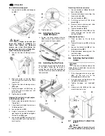
vide adequate protection against contact
with the band saw blade, it must always
be set as close as possible against the
work piece (distance 3 mm max.).
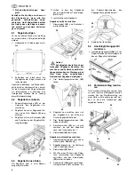
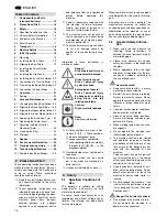
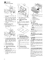
Lower blade guard
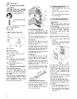
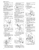
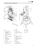
The lower blade guard
(35)
protects
against inadvertent contact with the
band saw blade below the saw table.
The lower blade guard must be installed
during operation.
Housing doors
The housing doors
(36)
protect against
contact with the rotating parts inside the
machine.
The housing doors are equipped with
interlocking contacts. These turn the
motor OFF when one housing door is
opened while the saw is running.
The housing doors must be closed while
the machine is in use.
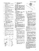
Push stick
The push stick serves as an extension of
the hand and protects against accidental
contact with the saw blade.
The push stick must always be used if
the distance between band saw blade
and a rip fence is less than 120 mm.
Guide the push stick at an angle of 20
q
… 30
q
against the saw table's surface.
When the push stick is not used it can be
stored on the push stick holder provided
at the band saw frame.
Replace push stick if damaged.
x
Set upper blade guide to its lowest
position.
x
Remove projecting accessories.
x
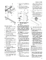
When shipping, use original packing
if possible.
3
Note:
In this chapter the essential oper-
ating elements of the machine are intro-
duced.
The proper use of the machine is
described in chapter "Operation". Read
this chapter before using the saw for the
first time.
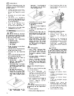
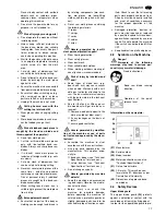
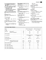
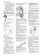
On/Off switch with emergency stop
x
To start = press the green switch
button
(38)
.
x
To stop = press the red switch but-
ton
(37)
or the cover
(39)
of the ON/
OFF switch.
In the event of a voltage failure an und-
ervoltage relay will trip. This prevents the
machine from starting up when the
power is restored. To restart, the green
switch button must be pressed.
The cover of the ON/OFF switch
(39)
can be safeguarded by a padlock.
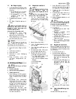
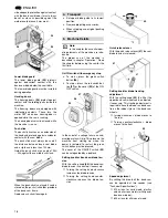
Setting knob for band saw blade ten-
sion
With the setting knob
(40)
the band saw
blade tension is corrected, if necessary:
Turning the setting knob clockwise
increases the blade tension.
Turning the setting knob counter-
clockwise reduces the blade ten-
sion.
Quick release lever
With the quick release lever
(41)
the saw
blade tension is released.
Setting knob for blade tracking
adjustment
With the setting knob
(42)
the tilt of the
upper band saw wheel can be adjusted,
if necessary. This tracking adjustment is
required to have the blade run dead cen-
tre on the rubber tyres of the band saw
wheels:
turning clockwise = blade moves to
the rear
Turning counter-clockwise = blade
moves to the front.
Speed adjustment
By shifting the drive belt the band saw
can be operated at two speeds (see
"Technical Specifications"):
370 m/min for hard wood, plastics
and non-ferrous metals (with special
band saw blade);
800 m/min for all kinds of wood.
34
35
36
4.
Transport
5.
Machine Details
37
38
39
40
41
42
Summary of Contents for BAS 317 Precision WNB
Page 53: ...ZA0091_1 fm 3 1 2 4 6 5 ...
Page 54: ......
Page 55: ......
Page 56: ...U4BA_M1 FM ZINDEL AG Technische Dokumentation und Multimedia www zindel de www metabo com ...

