19
ENGLISH
A
Caution!
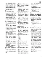
The drive belt must not run in a
diagonal position; this will damage
the belt
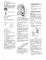
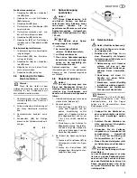
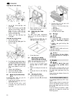
Setting knob for drive belt tension
With the setting knob
(43)
the drive belt
tension is corrected, if necessary:
turning the setting knob clockwise
reduces the blade tension;
turning the setting knob counter-
clockwise increases the blade ten-
sion.
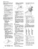
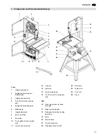
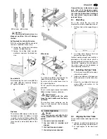
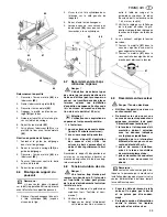
Saw table tilt
After loosening the lock screw
(44)
the
saw table
(45)
tilts steplessly through
47° against the blade.
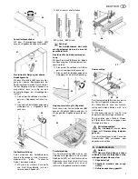
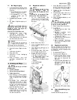
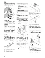
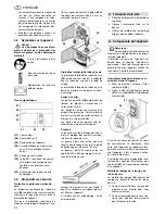
Rip fence
The rip fence
(46)
clamps to the front of
the bandsaw table; in addition it is held
in position by the hold-down clamp
(47)
at the rear of the bandsaw table. The rip
fence can be used on both sides of the
blade.
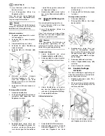
Mitre fence
The mitre fence
(49)
is inserted into the
table slot from the table’s front edge.
For mitre cuts the mitre fence turns to
60° in both directions.
For 45° and 90° miters positive stops are
provided.
To set a mitre angle: loosen lock handle
(48)
by turning it counter-clockwise.
A
Risk of injury!
When cutting with the mitre
fence the lock handle must be firmly
tightened.
The auxiliary fence extrusion can be
taken off and reversed after loosening
knurled nut
(50)
.
A
Danger!
Start the saw only after the fol-
lowing preparations have been com-
pleted:
the saw is securely mounted;
the saw table is installed and
aligned;
the V-belt tension checked;
the safety devices checked.
Connect the saw to the mains supply
only after all of the above prepara-
tions are completed! Otherwise there
is a risk of an unintentional starting of
the saw, which may cause serious
personal injury.
6.1
Mounting
For a firm stand the saw must be
mounted on a stable supporting surface:
1.
Drill four holes in the supporting sur-
face.
2.
Put fixing bolts through the base
plate and secure with nuts.
Optimal working height and stability is
provided by the steel stand, which is
already prepared for mounting the saw.
Information regarding the assembly of
the stand is given in the addendum to
these operating instructions.
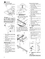
6.2
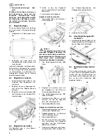
Installing the Saw Table
1.
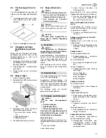
Fit limit stop screw
(51)
to the under-
side of the saw table.
2.
Guide saw table over the band saw
blade and place it on the table trun-
nion.
3.
Attach the saw table with four each
screws
(52)
and washers to the
table trunnion.
6.3
Aligning the Saw Table
The saw table needs to be aligned in two
planes
laterally, in order for the blade to run
dead centre through the table insert;
at right angles to the band saw
blade.
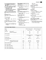
800 m/min
370 m/min
43
44
45
6.
Initial Operation
46
47
48
49
50
51
52
Summary of Contents for BAS 317 Precision WNB
Page 53: ...ZA0091_1 fm 3 1 2 4 6 5 ...
Page 54: ......
Page 55: ......
Page 56: ...U4BA_M1 FM ZINDEL AG Technische Dokumentation und Multimedia www zindel de www metabo com ...

