background image

ENGLISH

en

8

safety devices, protective devices or lightly 

damaged parts must be carefully inspected for 

correct and proper operation. A damaged 

device must only be reused after it has been 

correctly repaired.

– Check to see that all moving parts work properly 

and do not jam. All parts must be correctly 

installed and fulfil all conditions necessary to 

ensure perfect operation of the unit. 

– Damaged protection devices or parts must be 

repaired or replaced by a qualified specialist. 

4.5 Additional Safety Instructions

– Please also observe the special safety 

instructions in the respective chapters. 

– Observe any particular health and safety or 

accident prevention regulations governing the 

use of compressors and compressed air tools. 

– Observe the legal provisions for the operation of 

systems requiring monitoring.

– Keep in mind that escaping condensate and 

other consumables contaminate the 

surrounding area and may trigger damage to the 

environment during operation and storage of the 

tool.

– Consider environmental conditions:

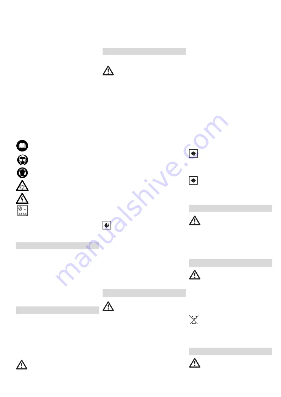
4.6 Symbols on the machine 

(depends 

on model)

Read the operating instructions. 

Wear eye goggles

Wear ear protectors.

Warning of automatic startup. 

Danger - electrical voltage. 

Guaranteed sound power level. 

4.7 Safety devices

Safety valve 

The spring-loaded valve (3) reacts if the permitted 

maximum pressure is exceeded. 

See page 2.

1 pressure vessel

2 condensate  outlet

3 safety valve

4 connection for compressed air (quick 

coupling), regulated compressed air

5 manometer control pressure

6 pressure  regulator

7 manometer boiler pressure

8 ON/OFF  Switch

9 transport handle

* depends on model / equipment

6.1 Check condensate outlet

Ensure that the condensate outlet (2) is closed.

6.2 Installation 

The positioning site of the device has to meet the 

following requirements:
– Dry, protected from frost
– Stable,  horizontal and even surface

Danger! 

Wrong positioning might cause serious accidents.
– Secure the device against rolling away, tilting 

and slipping.

– Safety installations and operating elements 

have to be easily accessible at any time.

6.3 Transport

– Do not pull the device from the hose or mains 

cable. Transport the device at the transport 

handle (9).

7.1 Power-supply connection

Danger! High voltage.

Operate the device in dry surroundings only. 
Operate the device only at a power source 

meeting the following requirements: Wall sockets 

installed according to regulations, earthed and 

tested; fuse protection according to the technical 

data. 
Position power supply cable so it does not 

interfere with the work and is not damaged.
Check every time if the device is switched off, 

prior to plugging the mains plug into the socket 

outlet. 
Protect power supply cable from heat, aggressive 

liquids and sharp edges.
Use only extension cables with sufficient core 

cross-section (see chapter 12. Technical Data).
Use extension cables for outdoor areas. When 

working outdoors, only use the correspondingly 

marked extension cable approved for this 

purpose.
Do not switch off the compressor by pulling the 

mains plug, but use the ON/OFF switch. 
Always install an RCD with a maximum trip 

current of 30 mA upstream.

7.2 Generate compressed air

1. Switch on the device using the ON/OFF switch 

(8)  and wait, until the maximum boiler 

pressure has been reached (compressor 

switches off). The boiler pressure is shown at 

the boiler pressure manometer (7) .

Set the control pressure at the pressure reducer 

(6) . The current control pressure is shown at the 

control pressure manometer (5) .

Attention!

The set control pressure must not exceed the 

maximum operating pressure of the connected 

compressed air tools!
2. Connect the compressed air hose at the 

compressed air inlet (4) .

3. Connect the compressed air tool. Now you 

can work with the compressed air tool.

4. Switch off the tool if you don't want to continue 

working immediately. Afterwards pull the 

mains plug.

5. Drain the condensed water of the pressure 

vessel at the condensate outlet (2) on a daily 

basis. 

Danger!

Prior to all servicing: 

Switch machine off. Disconnect the mains plug. 

Wait until the device has stopped. Ensure that 

there is no more pressure on the device and all 

used compressed air tools and accessories.
Leave the device and all used compressed air 

tools and accessories to cool down. 

After to all servicing: 

Put back into operation and check all safety 

installations. Ensure that there are no tools or 

similar at or in the device.
Repair and maintenance work other than 

described in this section should only be carried 

out by qualified specialists.

8.1 Important information

Maintenance and test have to be planned and 

carried out in accordance with the legal 

provisions in line with the setup and mode of 

operation of the device.
Regulatory authorities may ask to view respective 

documentation.

8.2 Regular maintenance 

Prior to every start

– Check compressed air hoses for damage and 

replace, if necessary. 

– Check that all screw fittings are seated securely, 

and tighten if necessary. 

– Check connection cables for damage, and, if 

necessary, have it replaced by a qualified 

electrician.

Daily

– Drain the condensed water of the pressure 

vessel at the condensate outlet (2).

8.3 Storage of device 

1. Switch off the device and pull mains plug.
2. Depressurise the pressure vessel and all 

connected compressed air tools.

3. Drain the condensed water of the pressure 

vessel at the condensate outlet (2). 

4. Store the device in such a way that 

unauthorised persons cannot start it. 

Attention!

Do not store the tool outdoors or in damp 

conditions without protection.

Danger of frost

Attention!

Frost (< 5 °C) destroys the pump and accessories 

as both always contain water! If there is a danger 

of frost disassemble pump and accessories and 

store in frost-free conditions. 

Danger! 

Repair of tools must be carried out by qualified 

electricians only! 
If you have Metabo devices that require repairs, 

please contact your Metabo service centre. See 

www.metabo.com for addresses.
You can download a list of spare parts from 

www.metabo.com.

Danger! 

The condensed water from the pressure vessel 

contains oil residue and /or contaminations 

hazardous to the environment. Dispose of the 

condensed water in an environmentally-friendly 

manner using respective collection sites!
Observe national regulations on environmentally 

compatible disposal and on the recycling of 

disused machines, packaging and accessories.

Only for EU countries: Never dispose of 

devices in your household waste! In 

accordance with European Guideline 2012/

19/EU on used electronic and electric equipment 

and its implementation in national legal systems, 

used devices must be collected separately and 

returned for environmentally compatible 

recycling.

Danger!

Prior to all servicing:

Switch machine off. Disconnect the mains plug. 

Wait until the device has stopped. Ensure that 

there is no more pressure on the device and all 

5. Overview

6. Commissioning

7. Operation

8. Care And Maintenance 

9. Repairs

10. Environmental Protection 

11. Troubleshooting

Summary of Contents for Basic 160-6 W OF

Page 1: ...leiding 16 it Istruzioni per l uso originali 20 es Manual original 24 pt Manual de instru es original 28 sv Originalbruksanvisning 32 fi Alkuper inen k ytt ohje 35 no Original bruksanvisning 38 da Ori...

Page 2: ...2 A Bild A B Bild B C Bild C D Bild D E Bild E F G 1 2 3 7 8 9 4 5 6 2...

Page 3: ...m kg 8 4 LpA KpA dB A 82 3 5 LWA KWA dB A 94 3 5 LWA G KWA G dB A 97 12 2 2011 65 EU 2006 42 EC 2014 30 EU 2000 14 EC 2005 88 EC 3 EN 1012 1 2010 EN 60204 1 2006 A1 2009 EN ISO 12100 2010 EN 50581 201...

Page 4: ...wissern Sie sich dass das Ger t ausgeschaltet ist bevor Sie es an die Stromversorgung anschlie en es aufnehmen oder tragen Wenn Sie beim Tragen des Ger tes den Finger am Schalter haben oder das Ger t...

Page 5: ...Wegrollen Umkippen und Rutschen Sicherheitseinrichtungen und Bedienelemente m ssen jederzeit gut zuganglich sein 6 3 Transport Ziehen Sie das Ger t nicht am Schlauch oder Netzkabel Ger t am Transport...

Page 6: ...auen Kondensat Ablass undicht Stellen Sie sicher dass der Kondensat Ablass 2 geschlossen ist Dichtung der Ablass Schraube pr fen ggf ersetzen R ckschlagventil undicht R ckschlagventil in Fachwerkstatt...

Page 7: ...air can be caught in moving parts h Do not let familiarity gained from frequent use of tools allow you to become complacent and ignore tool safety principles A careless action can cause severe injury...

Page 8: ...ure at the pressure reducer 6 The current control pressure is shown at the control pressure manometer 5 Attention The set control pressure must not exceed the maximum operating pressure of the connect...

Page 9: ...sel size a number of air outlets z number of cylinders n0 max speed P1 rated input power U connection voltage I rated power Fmin min fuse protection IP protection class G maximum overall length and co...

Page 10: ...ent le risque de blessure c vitez tout d marrage intempestif Veillez ce que l appareil soit teint avant de le brancher au courant de le prendre en main ou de le porter Si vous portez l appareil en aya...

Page 11: ...t de glisser Les dispositifs de s curit et les l ments de commande doivent toujours tre accessibles 6 3 Transport Ne pas tirer l appareil avec par le flexible ou le c ble d alimentation Transporter l...

Page 12: ...u le compresseur l aide de l interrupteur de marche arr t 8 Le compresseur fonctionne mais ne g n re pas suffisamment de pression Fuite au niveau de la sortie de condensat Veillez ce que la sortie de...

Page 13: ...het soort en gebruik van het gereedschap vermindert het risico op letsel c Voorkom per ongeluk inschakelen Verzeker u ervan dat het gereedschap uitgeschakeld is voordat u het op de stroomvoorziening a...

Page 14: ...foutieve installatie kunnen ernstige ongelukken ontstaan Beveilig het apparaat tegen wegrollen kantelen en glijden Veiligheidsvoorzieningen en bedieningselementen moeten vrij toegankelijk zijn 6 3 Tr...

Page 15: ...ten laten afkoelen Compressor met behulp van de aan uit schakelaar 8 opnieuw inschakelen Compressor draait zonder voldoende druk op te bouwen Condensventiel lekt Controleer of het condensventiel 2 ges...

Page 16: ...one elettrica e prima di prelevarlo o trasportarlo Trasportare il dispositivo tenendo il dito sopra l interruttore o collegare il dispositivo accesso all alimentazione di corrente comporta il pericolo...

Page 17: ...essere sempre facilmente accessibili 6 3 Trasporto Non tentare di spostare il dispositivo tirandolo per il tubo o per il cavo di alimentazione Per il trasporto utilizzare l apposita maniglia 9 7 1 Al...

Page 18: ...i che lo scarico della condensa 2 sia chiuso Controllare la guarnizione della vite di scarico e sostituirla all occorrenza Mancata tenuta della valvola di non ritorno Far revisionare la valvola di non...

Page 19: ...polvo zapatos de seguridad con suela antideslizante casco o protectores auditivos c Evite una puesta en marcha fortuita del aparato Aseg rese de que el aparato est apagado antes de conectarlo a la tom...

Page 20: ...cumplir los siguientes requisitos Seco y protegido contra heladas Superficie fija horizontal y plana Peligro Un montaje err neo puede causar accidentes graves Asegure el aparato frente a desplazamient...

Page 21: ...xi n 8 Eliminar la causa del sobrecalentamiento Hacer enfriar durante unos diez minutos Conectar de nuevo el compresor mediante el interruptor de conexi n desconexi n 8 El compresor funciona sin gener...

Page 22: ...ar Se ao transportar o aparelho tiver o dedo sobre o bot o ou se conectar o aparelho j ligado corrente el ctrica poder provocar acidentes graves d Remova as ferramentas de ajuste ou as chaves de fenda...

Page 23: ...ntos de comando devem estar sempre acess veis 6 3 Transporte Nunca dever puxar o aparelho pela mangueira ou pelo cabo de rede Transportar o aparelho pelo punho de transporte 9 7 1 Liga o rede Perigo T...

Page 24: ...ertifique se de que a descarga de condensado 2 est fechada Verificar a veda o do parafuso de descarga se necess rio substituir V lvula de retorno com fuga Rectificar a v lvula de retorno numa oficina...

Page 25: ...rollera maskinen i ov ntade situationer f B r l mpliga kl der B r inte l st h ngande kl der eller smycken H ll h ret och kl derna borta fr n r rliga delar L st h ngande kl der smycken och l ngt h r ka...

Page 26: ...tryckluft 1 Sl p maskinen med str mbrytaren 8 och avvakta tills max panntryck uppn tts kompressorn sl ngs av Panntrycket visas p panntrycksmanometern 7 St ll in styrtryck p tryckregleraren 6 Aktuellt...

Page 27: ...gd vid 80 max tryck p max tryck V pannstorlek a antal luftutg ngar z cylindertal n0 max varvtal P1 nominell effektf rbrukning U anslutningssp nning I m rkstr m Fmin min s kring IP skyddstyp G f rl ngn...

Page 28: ...tteen py riv n osaan voi aiheuttaa tapaturmia e V lt ep normaaleja ty skentelyasentoja Huolehdi aina tukevasta seisoma asennosta ja tasapainosta Siten voit paremmin hallita laitetta odottamattomissa t...

Page 29: ...riitt v katso luku 12 Tekniset tiedot K yt ulkok ytt n soveltuvia jatkojohtoja K yt ulkona vain t h n tarkoitukseen hyv ksyttyj ja vastaavasti merkittyj jatkojohtoja l kytke kompressoria pois p lt vet...

Page 30: ...lmaty kalun v linen letkuliitos vuotaa Tarkasta letkuliitos vaihda tarpeen vaatiessa vahingoittuneet osat uusiin Selitykset sivulla 3 annetuille tiedoille Pid t mme oikeuden tehd teknisen kehityksen v...

Page 31: ...kindel kan f re til skader e Unng unormal kroppsholdning S rg for st st dig og i balanse Dermed kan du kontrollere maskinen bedre i uventede situasjoner f Bruk alltid egnede kl r Ikke bruk vide kl r e...

Page 32: ...8 og vent til maksimalt kjeltrykk er oppn dd kompressor sl r seg av Kjeltrykket vises p kjeltrykkets manometer 7 Reguleringstrykk stilles inn p trykkregulator 6 Aktuelt reguleringstrykk vises p regule...

Page 33: ...elst rrelse a Antall luftavganger z Sylindertall n0 Maks turtall P1 Nominelt effektopptak U Forbindelsesspenning I Nominell str m Fmin Min sikring IP Beskyttelsesgrad G Maksimal total lengde og ledert...

Page 34: ...ykke v rkt j eller en n gle sidder i en roterende maskindel er der risiko for personskader e Undg en unormal kropsholdning S rg for at st sikkert mens der arbejdes og kom ikke ud af balance Det er der...

Page 35: ...12 Tekniske data Anvend forl ngerledninger til udend rs brug I det fri m der kun bruges forl ngerledninger som er godkendt til udend rs brug og m rket tilsvarende Undg at frakoble kompressoren ved at...

Page 36: ...dele Forklaringer til oplysningerne p side 3 Forbeholdt ndringer som f lge af tekniske fremskridt A Indsugningsydelse F P fyldningsydelse Leff Effektiv forsyningsm ngde ved 80 maks tryk p Maks tryk V...

Page 37: ...y indywidualnej i zawsze nosi okulary ochronne Stosowanie rodk w ochrony indywidualnej np maski przeciwpy owej obuwia roboczego z podeszw antypo lizgow kasku ochronnego lub ochronnik w s uchu w zale n...

Page 38: ...Manometr regulacji ci nienia 6 Regulator ci nienia 7 Manometr ci nienia wewn trz zbiornika 8 W cznik wy cznik 9 Uchwyt transportowy w zale no ci od modelu wyposa enia 6 1 Kontrola spustu kondensatu S...

Page 39: ...biorniku ci nieniowym Spr arka zosta a wy czona w trakcie pracy poprzez wyci gni cie wtyczki z gniazdka Wy czy najpierw spr ark za pomoc w cznika wy cznika 8 nast pnie ponownie w czy Przegrzanie silni...

Page 40: ...el 40 1 2 3 4 5 6 7 8 9 10 11 12 1 2 3 4 LWA M LWA G 5 6 4 3 1 3 2 3 3 ON OFF 3 4 3 5 Service 3 6 1 2 3...

Page 41: ...el 41 4 1 4 2 4 3 4 4 4 5 4 6 4 7 3 2 1 2 3 4 5 6 7 8 ON OFF 9 6 1 2 6 2 6 3 9 7 1 12 OFF FI RCD 30 mA 7 2 1 OFF 8 7 6 5 2 4 3 4 5 2 4 5 6 7 8...

Page 42: ...F 8 OFF 8 OFF 8 2 6 3 A F Leff 80 p V a z n0 P1 U I Fmin IP G A x x Tmax Tmin m LpA LWA LWA G 2000 14 KpA KWA A 9 10 11 12 1 230 V 50 Hz P 1 50 kW S 3 I 6 0 A IP 20 01532XX0 9998812345 Basic 250 24 W...

Page 43: ...el 43 B C D E F G H I CE J K L M N O P 10...

Page 44: ...l ket kikapcsolt k miel tt azt az ramforr sra csatlakoztatja vagy felemeli s sz ll tja Ha a k sz l k felemel se k zben az ujj t a kapcsol n tartja vagy ha a k sz l ket bekapcsolt llapotban csatlakozt...

Page 45: ...len A biztons gi berendez sek s kezel elemek b rmikor hozz f rhet ek kell legyenek 6 3 Sz ll t s Ne h zza a k sz l ket a t ml n l vagy a h l zati csatlakoz vezet kn l fogva Sz ll tsa a k sz l ket a sz...

Page 46: ...8 jra bekapcsolni A kompresszor megfelel nyom s fel p t se n lk l m k dik A kondenz tum leereszt s t m tetlen Gy z dj n meg arr l hogy a kondenz tum leereszt st 2 lez rt k A leereszt csavar t m t s t...

Page 47: ...ru 47 1 2 3 4 5 6 7 8 9 10 11 12 1 2 3 4 LWA M LWA G 5 6 4 3 1 c 3 2 a 3 3 3 4 3 5 a 3 6 1 2 3...

Page 48: ...ru 48 4 1 4 2 4 3 4 4 4 5 4 6 4 7 3 2 1 2 3 4 5 6 7 8 9 1 6 1 2 6 2 6 3 9 7 1 12 30 7 2 1 8 7 6 5 2 4 3 4 4 5 6 7...

Page 49: ...ru 49 5 2 8 1 8 2 2 8 3 1 2 3 2 4 5 C Metabo Metabo www metabo com www metabo com 2012 19 EU 12 8 8 8 2 6 3 A F Leff 80 p V a z n0 P1 U I Fmin IP G A x x Tmax Tmin m LpA 8 9 10 11 12...

Page 50: ...32 23 97 48 E mail ivfs mail ru RA RU 11 08 24 03 16 Metabowerke GmbH Metaboallee 1 D 72622 Nuertingen 127273 5 7 106 7 495 980 78 41 10 1 4 2014 2 3 05 1 5 1 230 V 50 Hz P 1 50 kW S 3 I 6 0 A IP 20 0...

Page 51: ......

Page 52: ...Metabowerke GmbH Metabo Allee 1 72622 Nuertingen Germany www metabo com 170 27 6820 0220...

Reviews: