background image

ENGLISH

en

10

KFM 15-10 F 

(see page 3, Fig. B):

Switching on: 

push the sliding switch (22) 

forwards. For continuous operation, now tilt it 

downwards until it engages.

Switching off: 

press the rear end of the slide switch 

(22) and release it.

KFMPB 15-10 F 

(see page 3, Fig. B):

Switching on: 

slide the paddle switch (23) in the 

direction of the arrow and then press the 

paddle switch (23).

Switching off: 

release the paddle switch (23).

KFM 16-15 F 

(see page 3, Fig. B):

Torque activation:
Switching on: 

press in the lock (24) and then press 

the trigger switch (25). Release the lock (24).

Switching off: 

release the trigger switch (25).

Continuous operation:
Switching on: 

press in the lock (24) and hold it in 

place. Press and hold in the trigger switch 

(25). The machine is now switched on. Now 

press in the lock (24) once more to lock the 

trigger (25) (continuous operation).

Switching off:

 press the trigger switch (25) and 

release.

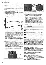
7.2 Setting speed (KFM 15-10 F)

The speed can be preset via the speed adjustment 

wheel (10) and is infinitely variable. 
Positions 1-6 correspond approximately to the 

following no-load speeds:
1 ........ 7800 / min

4....... 10200 / min

2 ........ 8600 / min

5....... 11100 / min

3 ........ 9400 / min

6....... 12200 / min

The VTC electronics make material-compatible 

work possible and an almost constant speed, even 

under load. 
Speed recommendations for different materials:
Aluminium, copper, brass.............................. 4-6

Steel up to 58.015 psi  ................................... 4-6

Steel up to 87.022 psi  ................................... 3-5

Steel up to 130.534 psi  ................................. 2-4

Stainless steel ............................................... 1-3

The best way to determine the ideal setting is 

through a practical trial.

7.3 General working instructions

1. Check the indexable inserts (20). Change 

damaged or worn indexable inserts.

2. Fix workpiece without vibrations using clamping 

devices.

3. Pay attention to chapter 7.4 when working on 

pipes.

4. Set the chamfer angle (see chapter 6.1).

5. Set the chamfer height (see chapter 6.2).

6. Always hold the machine with both hands on the 

designated handles, take a secure stance and 

concentrate on the work.

7. The indexable inserts (20) do not touch the 

workpiece. First switch on, then place the 

machine with the guide rail (15) onto the 

workpiece and only then put the tool close to the 

workpiece.

8. Slide the machine only in the direction specified 

by an arrow on the machine (16).

Slide the machine only in the direction of 

the arrow (16). Otherwise there is the risk 

of kickback. Guide the machine evenly at a 

speed suitable for the material being processed. 

Do not tilt, apply excessive force or sway from 

side to side.

9. Guide the machine in such a way that the guide 

rail (15) is in contact with the workpiece.

10.Finishing the work: remove the tool from the 

workpiece, switch off machine. Let motor come 

to a stop, put down machine.

7.4 Working on the outer edge of pipes

1. Determine the diameter of the pipe to be worked 

on.

2. See page 3, Fig. C: attach the guide roller (26) to 

the guide rail (15) as shown. Move the guide 

roller (26) and adjust on the scale (27) on the 

pipe diameter. Tighten the guide roller nut with a 

spanner and thus tighten the guide roller.

3. Pay attention to the general working instructions 

(chapter 7.3).

4. Always hold the machine with both hands on the 

designated handles, take a secure stance and 

concentrate on the work.

5. Place the machine with the guide roller (26) on 

the outer surface of the pipe. Then place the 

guide rail on the surface of the pipe end.

6. The indexable inserts (20) do not yet touch the 

workpiece. First switch on, then slowly tilt the 

machine around the guide roller (26) to move the 

milling head close to the workpiece.

7. Pay attention to the general working instructions 

(chapter 7.3).

7.5 KFM 16-15 F: Possibility for rotating the 

guide rail (15)

The guide rail (15) of the KFM 16-15 is installed 

transversely. This permits better absorption of high 

forces and permits low-fatigue working for most 

tasks. 
If you prefer to install the guide rail (15) in a 

longitudinal manner, the Metabo customer service 

will provide you with conversion instructions on 

request.

8.1 Changing indexable inserts

Pull the plug out of the socket before making 

any adjustments, changing tools, carrying out 

maintenance or cleaning.

Indexable inserts, holders for indexable 

inserts, the workpiece and chips can be hot 

after work. Wear protective gloves.

8. Maintenance

Summary of Contents for KFM 15-10 F

Page 1: ...www metabo com Made in Germany KFM 15 10 F KFMPB 15 10 F KFM 16 15 F en Operating Instructions 5 fr Mode d emploi 13 es Instrucciones de manejo 22...

Page 2: ...KFM 15 10 F KFMPB 15 10 F 13 7 6 8 9 12 11 10 17 18 14 15 16 16 1 1 2 2 3 4 5 21 20 19 A 2...

Page 3: ...0 I 10 KFM 15 10 F KFMPB 15 10 F KFM 16 15 F 26 25 24 23 22 27 0 I B C 3...

Page 4: ...900 hmax 45 in mm 3 8 10 3 8 10 19 32 15 hmax 30 in mm 1 2 13 1 2 13 25 32 20 bmax 45 in mm 9 16 14 9 16 14 13 16 21 a 0 90 0 90 0 90 dmin in mm 2 15 16 75 2 15 16 75 3 15 16 100 m lbs kg 10 8 4 9 11...

Page 5: ...ntering a power tool will increase the risk of electric shock d Do not abuse the cord Never use the cord for carrying pulling or unplugging the power tool Keep cord away from heat oil sharp edges or m...

Page 6: ...ecause the accessory can be attached to your power tool it does not assure safe operation b Do not use damaged power tools Before use check the indexable inserts for chipping cracks or signs of severe...

Page 7: ...tool live and shock the operator Keep the work area clean and well lit Cluttered or dark areas invite accidents WARNING Always wear protective goggles Wear ear protectors Pull the plug out of the sock...

Page 8: ...GFCI with a maximum trip current of 30 mA upstream 5 1 Attaching the additional handle Only work with attached bow handle 1 or side handle 5 depending on equipment Attach the handle as shown see page...

Page 9: ...from this intersection to the X axis Read the value on the X axis You must now set this X value as follows on the machine Note The diagram is based on sharp edged workpieces For workpieces with round...

Page 10: ...n then place the machine with the guide rail 15 onto the workpiece and only then put the tool close to the workpiece 8 Slide the machine only in the direction specified by an arrow on the machine 16 S...

Page 11: ...ned sufficiently Replace the strongly worn indexable inserts Pull the mains plug out of the socket Chips and particles can deposit at the milling head 19 This can lead to blockage of the milling head...

Page 12: ...ble The technical specifications quoted are subject to tolerances in compliance with the relevant valid standards Emission values These values make it possible to assess the emissions from the power t...

Page 13: ...tr le de l outil 2 2 S curit lectrique a Il faut que les fiches de l outil lectrique soient adapt es au socle Ne jamais modifier la fiche de quelque fa on que ce soit Ne pas utiliser d adaptateurs ave...

Page 14: ...Utiliser l outil les accessoires et les lames etc conform ment ces instructions en tenant compte des conditions de travail et du travail r aliser L utilisation de l outil pour des op rations diff rent...

Page 15: ...support de plaquette amovible peut sauter en direction de l op rateur ou s en loigner selon le sens du mouvement de la plaquette amovible au point de blocage Dans de telles conditions les plaquettes...

Page 16: ...Veiller ce que les tincelles et les copeaux chauds produits lors de l utilisation ne provoquent aucun risque par ex celui d atteindre l utilisateur ou d autres personnes ou d enflammer des substances...

Page 17: ...droit de la machine D brancher le cordon d alimentation de la prise de courant avant toute op ration de r glage de changement d accessoire de maintenance ou de nettoyage Les plaquettes amovibles les...

Page 18: ...de chanfrein doit tre r gl e tr s exactement proc der comme suit R aliser un chanfrein d essai Mesurer la hauteur de chanfrein frais e et si besoin adapter la graduation d chelle en tournant l anneau...

Page 19: ...ine de travers ne pas l appuyer ni la faire osciller 9 Guider la machine de mani re ce que le rail de guidage 15 se trouve contre la pi ce usiner 10 Terminer le travail loigner l accessoire de la pi c...

Page 20: ...d appui suffisante et ne peuvent donc pas tre suffisamment fix es Remplacer les plaquettes amovibles trop us es D brancher la fiche secteur de la prise de courant Les copeaux et les particules peuven...

Page 21: ...le de chanfrein dmin diam tre minimal du tuyau m poids sans c ble d alimentation Les caract ristiques techniques indiqu es sont soumises tol rance selon les normes en vigueur correspondantes Valeurs d...

Page 22: ...guridad el ctrica a El enchufe de la herramienta el ctrica debe corresponder a la toma de corriente utilizada No es admisible modificar el enchufe en forma alguna No emplee adaptadores con herramienta...

Page 23: ...tes rotas o deterioradas que pudieran afectar a su funcionamiento Si la herramienta el ctrica estuviese defectuosa h gala reparar antes de volver a utilizarla Muchos de los accidentes se deben a apara...

Page 24: ...s El contragolpe es la reacci n s bita dada por una herramienta rotatoria bloqueada o enganchada El enganchamiento o bloqueo conlleva a una parada abrupta de la herramienta en rotaci n A su vez se gen...

Page 25: ...e protecci n para los o dos La exposici n a niveles de ruido elevados durante per odos prolongados puede causar da os en la capacidad auditiva Utilizar nicamente plaquitas afiladas que no presenten da...

Page 26: ...ornillos de mariposa 3 a la derecha y a la izquierda con la mano Montaje del mango lateral 5 depende del modelo solo con KFM 15 10 F KFMPB 15 10 F Cuando se est n fresando bordes con ngulos peque os a...

Page 27: ...ustar la altura del chafl n 5 Tirar del anillo de ajuste 7 hacia arriba y girar de tal forma que en la escala 9 est ajustado el valor X a partir del diagrama V ase la figura abajo valor X ajustado 2 0...

Page 28: ...no tocan la pieza de trabajo Primeramente encender la m quina despu s colocarla con el carril gu a 15 sobre la pieza y solo entonces empezar a introducir lentamente la herramienta de inserci n en la p...

Page 29: ...a apretar de nuevo la plaquita intercambiable 20 con el tornillo de fijaci n 21 Par de giro 3 5 Nm 7 Desplazar la chapa de protecci n contra virutas 14 totalmente hacia abajo Apretar los tornillos 13...

Page 30: ...ina www metabo com encontrar las direcciones correspondientes En la p gina www metabo com puede usted descargarse las listas de repuestos Cumpla lo estipulado por las normativas nacionales relativas a...

Page 31: ......

Page 32: ...0 12 14 16 18 20 22 24 0 0 1 0 2 0 3 0 4 0 5 0 6 0 h mm x mm One Touch Controller KFM 15 10 F KFMPB 15 10 F a 15 a 75 a 30 a 45 a 60 0 2 4 6 8 10 12 14 16 18 20 22 24 26 28 30 0 00 1 00 2 00 3 00 4 00...

Reviews: