


ENGLISH
en
9
also set the chamfer height again every time you
adjust the chamfer angle. See chapter 6.2
6.2 Setting the chamfer height
Set the chamfer angle first:
1. First check that the desired chamfer angle is set:
read the set chamfer angle on the scale (17).
Adjust if necessary. See chapter 6.1
Determining the setting value:
Note:
always produce large chamfer heights in
several milling operations (at least 3). Hard
materials require more milling operations. This has
the following advantages: a higher indexable insert
service life, work results with a higher surface
quality, more pleasant working conditions.
Do not exceed the "maximum chamfer height
per milling operation" specified below.
KFM 15...(at 45°):
1st milling operation: max. 6 mm
2nd +3rd milling operation: max. 2 mm
KFM 16...:(at 45°)
1st milling operation: max. 9 mm
2nd +3rd milling operation: max. 3 mm
Do not exceed the maximum permitted chamfer
height (h
max
) (see the Technical Specifications
chapter).
It is recommended that very little material is
removed during the last milling operation to ensure
an optimum surface quality.
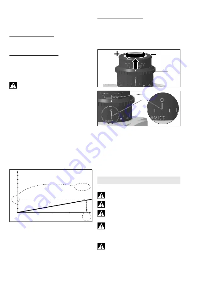
2. Select the diagram that applies to your machine
(see back).
3. Select the line that applies to the set chamfer
angle (see back).
4.
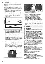
Example
for a chamfer angle of 45° and a
desired chamfer height of 3 mm (see figure
below). Result: setting value = 2.0.
Select the chamfer height that you want to set on
the Y-axis. Draw a horizontal line to the
intersection with the line. Draw a vertical line
from this intersection to the X-axis. Read the
value on the X-axis. You must now set this "X"
value as follows on the machine.
Note:
The diagram is based on sharp-edged
workpieces. For workpieces with rounded
edges, the milling height must be taken into
account during setting.
Setting the chamfer height:
5. Pull the adjusting ring (7) upwards and turn it so
that the "X" value from the diagram is set on the
scale (9). See figure (below): set "X" value = 2.0.
(One revolution corresponds to "X"=3. For large
X values: perform several revolutions. The scale
(6) is used for rough orientation during the
6. Carry out a trial cut.
7. Proceed as follows if the chamfer height should
be set very accurately for the last milling
operation:
Carry out a trial cut. Measure the cut chamfer
height and adjust it by one scale mark if
necessary by turning the adjusting ring (7):
clockwise rotation = larger chamfer height.
Anticlockwise rotation = lower chamfer height.
Carry out another trial cut. Repeat this step if
necessary.
7.1 Switching on and off
Always guide the machine with both hands.
Switch on first, then guide the accessory
towards the workpiece.
Avoid inadvertent starts: always switch the
tool off when the plug is removed from the
mains socket or if there has been a power cut.
In continuous operation, the machine
continues running if it is forced out of your
hands. Therefore, always hold the machine with
both hands using the handles provided, stand
securely and concentrate.
Avoid the machine swirling up or taking in dust
and chips. After switching off the machine,
only place it down when the motor has come to a
standstill.
0
3
2,0
0
,
1
0
X
Y
h (mm)
a = 45°
7. Use
6
8
1.
2.
8
5


