


ENGLISH
en
14
Observe the relevant guidelines for your
material, staff, application and place of
application (e.g. occupational health and safety
regulations, disposal).
Collect the generated particles at the source,
avoid deposits in the surrounding area.
Use the supplied dust collection unit and a
suitable extraction unit. This ensures that fewer
particles enter the environment in an
uncontrolled way.
Reduce dust exposure with the following
measures:
– Do not direct the escaping particles and the
exhaust air stream at yourself or nearby
persons or on dust deposits.
– Use an extraction unit and/or air purifiers
– Ensure good ventilation of the workplace and
keep clean using a vacuum cleaner Sweeping
or blowing stirs up dust
– Vacuum or wash the protective clothing Do not
blow, beat or brush
Hazard generated by modification of
the machine or use of parts not tested and
approved by the equipment manufacturer!
Assemble tool in strict accordance with these
instructions.
Use only parts approved by the equipment
manufacturer. This applies especially for:
– saw blades (for order numbers, refer to
– Safety devices.
– Cutting laser
– Illumination of cutting line
Do not change any parts.
Ensure that the speed indicated on the saw
blade is at least the same as the speed
indicated on the saw.
Hazard generated by tool defects!
Before every use check tool for possible
damage: before operating the tool all safety
devices, protective guards or slightly damaged
parts need to be checked for proper function as
specified. Check to see that all moving parts
work properly and do not jam. All parts must be
correctly installed and fulfil all conditions
necessary to ensure perfect operation of the
unit.
Do not used any damaged or contorted saw
blades.
Risk of injury by noise!
Wear hearing protection.
Danger from blocking workpieces or
workpiece parts!
If blockage occurs:
1. switch machine off,
2. Pull the mains plug or remove the detachable
battery pack,
3. wear gloves,
4. clear the blockage using a suitable tool.
4.2 Special safety instructions for
cordless machines:
Remove the battery pack from the machine before
making any adjustments, changing tools,
maintaining or cleaning.
Protect battery packs from water and
moisture!
Do not expose battery packs to fire!
Do not use faulty or deformed battery packs!
Do not open battery packs!
Do not touch contacts or short-circuit battery
packs!
A slightly acidic, flammable fluid may leak
from defective Li-ion battery packs!
If battery fluid leaks out and comes into
contact with your skin, rinse immediately
with plenty of water. If battery fluid leaks out
and comes into contact with your eyes, wash them
with clean water and seek medical attention
immediately!
4.3 Symbols on the machine
(depends
on model)
Read the operating instructions.
Never place hands into running saw
blade.
Wear protective goggles and ear
protectors.
Never operate the tool in a damp or wet
environment.
Laser radiation - Do not look
into the light beam.
LASER CLASS 2
4.4 Safety devices
The retractable blade guard protects against
unintentional contact with the saw blade and from
chips flying about.
Cordless tools: The machine can only be
switched on when the safety lock is activated.
Mains-powered tools: The retractable blade
guard opens and the saw can be lowered only
when the safety lock is activated.
Parallel guide/ ripping fence (26)
The parallel guide/ ripping fence prevents that the
workpiece can be moved during the cutting
process. During operation, the parallel guide/
ripping fence always has to be installed.
Make sure the additional profile
correctly to support the workpiece in the best
manner possible and will not interfere with the
blade or the guard. Lock using the set screw
.
The additional profile
at the parallel guide/
ripping fence has to be moved for inclined cuts
after loosening the set screw
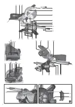
See page 2.
1 Closing the chip bag
2 Chip bag
3 Chip extraction nozzle
4 Laser beam egress point
5 Cutting line illumination
6 Retractable blade guard
7 Longitudinal stop
8 Table
9 Turntable
10 Table insert
11 Locking lever for turntable
12 Safety catch for stop positions of the turntable*
13 Set screw for pulling device*
14 Allen key / tool storage for Allen key
15 Work clamp
16 Table extension
17 Locking screw of the table width extension
18 Saw blade lock
19 Saw handle
20 Speed adjustment wheel *
21 Handle
22 Hook for cable winding
23 Locking lever for setting the angle of inclination
24 Locking button (to extend the angle of
inclination by +/- 2 °)
25 Transport lock
26 Parallel guide / ripping fence
27 Safety lock
28 On/off switch of the saw
29 On/off switch of the cutting laser
30 On/off switch of the cutting line illumination
31 Battery pack release button *
32 Capacity indicator button *
33 Capacity and signal indicator *
34 Battery pack*
* depends on model / equipment
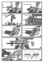
Install handle (21) if required (depending on
model)
Fix the handle
Install table width extension (16) if required
(depending on model)
1. Remove right and left table width extension
from the transport packaging.
2. Remove screws
right and left table width extension.
3. Push the guide rails of the table width
extensions completely into the recesses.
Insert the table width extension with folding
length guide
on the right side.
4. Lift the device at the front legs, carefully tilt it
backwards and put it down so it will not fall
over.
5. Tighten again the screws
rails.
6. Take the front legs of the device, carefully tilt it
forwards and put down.
7. Set the desired table width and lock the table
width extensions with locking screws
.
Installation
The device has to be mounted on a stable
support for safe working.
– The support can be either a firmly mounted work
top or work bench.
– Even when machining larger workpieces the
device has to have a secure stand.
– Long workpieces must get additional support
with suitable accessories.
Note:
For mobile use, the device can also be fixed to a
plywood or coreboard panel (500 mm x 500 mm,
at least 19 mm thick) using screws. During use,
the panel has to be fixed to a work bench using
screw clamps.
1. Fix device to the support using screws.
2. Loosen transport lock
slightly downwards and hold. Pull out transport
3. Swivel saw head slightly upwards.
Transport
1. Swivel saw head downwards and push in
transport lock
2. Lock the pulling device in the front position
using the set screw
Caution!
Do not hold the saw at the protective installations
during transport.
3. Lift the device at the handle
7.1 On/Off switch motor
Switching on the motor:
Press the on/off switch and keep pressed.
Switching off the motor:
Let go of the on/off switch.
7.2 On/off switch cutting line
Switching on/ off the illumination of the cutting
line.
Danger!
Do not direct the light beam into the eyes of
people or animals.
Note:
Cordless devices: During a short break the cutting
line illumination goes off (sleep mode) and is
automatically reactivated when resuming work. In
case of a long break the cutting line illumination
switches off automatically. Reactivation: Use
switch
.
5. Overview
6. Setup and transport
7. The device in detail


