


ENGLISH
en
15
7.3 On/off switch cutting laser
Switching on/off of the cutting laser.
The cutting laser marks a line to the left of the
saw's cut. Make a trial cut to become familiar with
the positioning.
Danger!
LASER BEAM
DO NOT LOOK INTO THE BEAM
LASER CLASS 2
EN 60825-1:2014
P<1mW,
λ
=650nm
Note:
Cordless devices: During a short break the cutting
laser goes off (sleep mode) and is automatically
reactivated when resuming work. In case of a
long break the cutting laser switches off.
7.4 Setting the angle of inclination
After loosening the locking lever
can be infinitely inclined between 0° and 45° to
the left of the vertical position
adjustment process in order to also set angles up
to 47° to the left of the vertical/ up to 2° to the right
of the vertical.
Danger!
In order for the angle of inclination not to change
when cutting, the locking lever
arm has to be tightened.
You can adapt the position of the locking lever
according to your requirements: pull out locking
lever, turn and push in the desired position and let
engage.
7.5 Turntable
After loosening the locking lever
activating the safety catch
be turned by 47° to the left or by 47° to the right
for mitre cuts. In this manner the cutting angle to
the support edge of the workpiece is adjusted.
Danger!
In order for the mitre angle not to change during
cutting, the locking handle
to be tightened (also in the stop positions!).
7.6 Pulling device
Using the pulling device, also larger workpieces
with greater cross sections can be cut. The
pulling device can be used for all types of cuts
(straight cuts, mitre cuts, slanted cuts and double
mitre cuts, and cutting of grooves).
If the pulling device is not required, lock the
pulling device in the rear position using the set
screw
.
7.7 Cutting depth limitation
Together with the pulling device the cutting depth
limitation
permits the cutting of grooves.
Turn the set screw and fix with the counter nut.
The cutting depth limitation can be deactivated, if
is pushed towards the rear.
7.8 Setting the speed
only for KGSV 216 M,
KGSM 216 Vario Max)
Select the speed at the setting wheel
. See
table for recommended setting wheel positions.
Wood: . . . . . . . . . . . . . . . . . . . . . . . . . . . . . . 3 - 6
Aluminium: . . . . . . . . . . . . . . . . . . . . . . . . . . 3 - 6
Plastic: . . . . . . . . . . . . . . . . . . . . . . . . . . . . . 1 - 3
8.1 Connect chip sack / chip and dust
extraction unit
Danger!
Dust of certain timber species (e.g. beech, oak,
ash) can cause cancer when inhaled.
– Only use a suitable dust extraction unit or
installed dust sack.
– In addition, use a dust mask, as not all saw dust
is collected or extracted.
– Regularly empty the dust sack. Wear a dust
mask while emptying the sack.
If you operate the device with the supplied dust
sack:
adapter nozzle
If you connect the device to a dust extraction unit:
Use a suitable adapter to connect it to the chip
extraction adapter nozzle (see chapter 12.
"Accessories").
Ensure that the dust extraction unit meets the
requirements stated in chapter 16. "Technical
Specifications".
Observe the dust collector's operating
instructions as well!
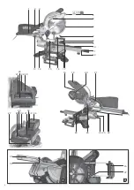
8.2 Installing the workpiece clamping
device
installed in two positions:
– For wide workpieces:
Insert the workpiece clamping device into the
rear drilling
– For narrow workpieces:
Insert the workpiece clamping device into the
front drilling
8.3 For mains powered machines only
Danger! High voltage
Operate machine only on a power source meeting
the following requirements (see also chapter 16.
"Technical Specifications"):
– Mains voltage and system frequency must
conform to the voltage and frequency shown on
the machine´s rating label;
– fuse protection by a residual current operated
device (RCD) of 30 mA sensitivity;
– outlets properly installed, earthed or grounded,
and tested.
Position power supply cable so it does not
interfere with the work and is not damaged.
Use only rubber-jacketed extension cables with
sufficient lead cross-section (3 × 1.5 mm
2
).
Use extension cables for outdoor areas. When
working outdoors, only use the correspondingly
marked extension cable approved for this
purpose.
Avoid accidental start-up. Ensure that the on/off
switch is switched off when inserting the plug in
the socket.
8.4 For cordless machines only
Avoid accidental start-up. Before fitting the
battery pack, make sure that the machine is
switched off.
Battery pack
Charge the battery pack
If performance diminishes, recharge the battery
pack.
The ideal storage temperature is between 10°C
and 30°C.
Li-Ion battery packs "Li-Power" have a capacity
and signal indicator
charge level.
- If one LED is flashing, the battery pack is almost
flat and must be recharged.
Removing and inserting the battery pack
Removal: Press the battery pack release button
(31)
and pull out the battery pack
towards the
rear.
To insert: Slide the battery pack
engages.
Before starting work, check to see that the
following are in proper working order.
Assume proper operating position:
– at the front of the saw;
– in front of the saw;
– next to the line of cut.
Danger!
If possible, fix the workpiece using the workpiece
clamping device
Danger of crushing!
When inclining or swivelling the saw head, never
reach into the hinge area or below the device!
Hold the saw head during inclination.
Use during work:
– workpiece support – for long workpieces, if
otherwise workpiece would fall off the table
after cutting;
– dust sack or dust extraction unit.
Cut only workpieces of dimensions that allow for
safe and secure holding while cutting.
Always hold the workpiece down on the table
and do not jam it. Do not attempt to stop the saw
blade by pushing the workpiece against its side.
Risk of personal injury if the saw blade is
blocked.
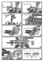
9.1 Straight cuts
Starting position:
– Transport lock
– Saw head swivelled upwards.
– Cutting depth limitation
deactivated.
– Turntable is in 0
°
for turntable is tightened.
– The inclination of the swivel arm to the vertical is
0
°
for inclined position is
tightened.
– Pulling device at the very rear.
– Set screw
of the pulling device has been
– Set workpiece stop
Release locking screw
workpiece is supported in the best manner
possible and will not interfere with the blade or
the guard. Fasten with locking screw
Cutting the workpiece:
1. Push the workpiece against the parallel guide/
ripping fence and clamp using the workpiece
clamping device
.
2. For wider workpieces: pull the saw head
forwards (towards the operator) (pulling
device).
3. Activate the safety lock
,press on/off
4. Slowly lower the saw head at the handle all the
way down and, if required, push towards the
rear (away from the operator). During the
sawing process press on the workpiece just
enough for the motor speed not to lower too
much.
5. Cut the workpiece in one operation.
6. Release the on/off switch
the saw head swivel back into the upper
starting position.
9.2 Mitre cuts
Starting position:
– Transport lock
– Saw head swivelled upwards.
– Cutting depth limitation
deactivated.
– Inclination of the swivel arm to the vertical is 0°,
tightened.
– Pulling device at the very rear.
– Set screw
of the pulling device has been
loosened.
– Set workpiece stop
Release locking screw
workpiece is supported in the best manner
possible and will not interfere with the blade or
the guard. Fasten with locking screw
.
8. Commissioning
9. Operation


