


ENGLISH
en
16
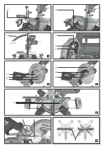
Cutting the workpiece:
1. Loosen locking lever
loosen safety catch
2. Set the desired angle.
3. Tighten the locking button
of the
turntable.
4. Cut workpiece, as described for "Straight
cuts".
9.3 Inclined cuts
Starting position:
pulled out.
– Saw head swivelled upwards.
– Cutting depth limitation
– Turntable is in 0
°
position, locking button
for turntable is tightened.
– Set screw
of the pulling device has been
– Pulling device at the very rear.
– Set workpiece stop
:
Release locking screw
. Move the
additional profile
workpiece is supported in the best manner
possible and will not interfere with the blade or
the guard. Fasten with locking screw
For particular angle settings it might be
necessary to completely pull out the additional
, after loosening the locking screw
. (After the
saw cut, reattach the additional profile
fasten with locking screw
lost.)
Cutting the workpiece:
1. Loosen the locking lever
for the
inclination setting at the rear side of the saw.
2. Slowly tilt the swivel arm into the desired
position.
3. Tighten the locking lever
for the
inclination setting.
4. Cut the workpiece, as described for "Straight
cuts".
9.4 Double mitre cuts
Note:
The double mitre cut is a combination of mitre cut
and inclined cut. This means, the workpiece is cut
at an angle to the rear contact edge
and
at an
angle to the top.
Danger!
With a double mitre cut, the saw blade is easier
accessible due to the steep inclination – this
results in a higher risk of injury. Always keep
sufficient distance to the saw blade!
Starting position:
pulled out.
– Saw head swivelled upwards.
– Cutting depth limitation
– Lock the turn table in the desired position.
– Swivel arm inclined at desired angle to the
workpiece surface and locked.
– Set screw
of the pulling device has been
– Pulling device at the very rear.
– Set workpiece stop
:
Release locking screw
. Move the
additional profile
workpiece is supported in the best manner
possible and will not interfere with the blade or
the guard. Fasten with locking screw
For particular angle settings it might be
necessary to completely pull out the additional
, after loosening the locking screw
. (After the
saw cut, reattach the additional profile
fasten with locking screw
lost.).
Cutting the workpiece:
Cut the workpiece, as described for "Straight
cuts".
9.5 Cutting grooves
Note:
The cutting depth limitation together with the
pulling device permits the cutting of grooves. This
does not result in a separating cut, but only a cut
of a certain depth is effected in the workpiece.
Risk of kickback!
When cutting grooves it is particularly important
that no lateral pressure is exerted on the saw
blade. Otherwise, the saw head might suddenly
kick back! Use a clamping device when cutting
grooves. Avoid lateral pressure on the saw head.
Starting position:
– Saw head swivelled upwards.
– Swivel arm inclined at desired angle to the
workpiece surface and locked.
– Lock the turn table in the desired position.
– Set screw
of the pulling device has been
– Pulling device at the very rear
Cutting the workpiece:
1. Set the cutting depth limitation
desired cutting depth and fix with counter nut.
downwards to check the set cutting depth:
3. Effect trial cut.
4. If required, repeat steps 1 and 3 until the
desired cutting depth has been set.
5. Cut the workpiece, as described for "Straight
cuts".
Danger!
Prior to all maintenance and cleaning jobs pull the
mains plug or remove the detachable battery
– Repair and maintenance work other than
described in this section should only be carried
out by qualified specialists.
– Replace damaged parts, in particular safety
installations, only with original parts. Parts not
approved by the equipment manufacturer can
cause unforeseeable damage.
– Check that all safety devices are operational
again after each service.
10.1 Saw blade change
Risk of burning!
Directly after cutting the saw blade can be very
hot. Let a hot saw blade cool down. Do not clean
the hot saw blade with combustible liquids.
Risk of injury, even with the blade at
standstill!
When loosening and tightening the tensioning
be swivelled over the saw blade. Wear gloves
when changing blades.
1. Pull the mains plug or remove the detachable
battery pack
.
2. Put the saw head in the upper position.
3. Lock saw blade: press the locking button
and turn the saw blade with the other hand
until the locking button engages. Hold down
the locking button.
4. Remove the tensioning screw with washer
(44)
on the saw blade shaft with Allen key
in clockwise direction (left-hand thread!).
powered devices) and push the retractable
blade guard
upwards and hold.
6. Carefully remove outer flange
from the saw blade shaft and close
again the retractable blade guard.
Danger!
Do not use cleaning agents (e.g. to remove resin
residue) that could corrode the light metal
components of the saw; the stability of the saw
would be adversely affected.
7. Cleaning the clamping surfaces:
– saw blade
– outer flange
– inner flange
Danger!
Place inner flange properly! If this is not the case,
the saw can block or the saw blade could work
loose. The inner flange is in the correct position if
the ring groove points towards the saw blade and
the flat side to the motor.
8. Put on inner flange
9. Loosen safety lock
powered devices) and push the retractable
10.Place a new saw blade - pay attention to
direction of rotation: Seen from the left (open)
side, the arrow on the saw blade has to
correspond to the direction of the arrow
on the saw blade cover!
Danger!
Use only saw blades, which fulfil the requirements
and specifications listed in these operating
instructions.
Use only saw blades designed for the maximum
speed (see "Technical Specifications") – if
unsuitable or damaged saw blades parts are
used, parts can be ejected due to centrifugal
force in an explosive-type manner.
Saw blades intended for cutting wood or similar
materials have to conform to EN 847-1.
Do not use:
– saw blades made of high-alloy speed steel
(HSS);
– damaged saw blades;
– cut-off wheel blades.
Danger!
– Mount saw blade using only genuine parts.
– Do not use loose-fitting reducing rings; the saw
blade could work loose.
– Saw blades have to be mounted in such way
that they do not wobble or run out of balance
and cannot work loose during operation.
11.Close again retractable blade guard
.
13.Put on the tensioning screw with the washer
(44)
in anti-clockwise direction (left-hand
14.Lock saw blade: press the locking button
and turn the saw blade with the other hand
until the locking button engages. Hold down
the locking button.
Danger!
– Do not extend the hexagon wrench.
– Do not tighten the tensioning screw by hitting
the hexagon wrench.
15.Firmly tighten the tensioning screw
the hexagon wrench
16.Check function. Loosen the safety lock
(only for mains-powered devices) and fold the
saw downwards:
– when folding down the retractable blade
guard, it has to provide free access to the saw
blade without touching other parts.
– When folding the saw upwards into the
starting position, the retractable blade guard
has to cover the saw blade automatically.
10. Care And Maintenance


