background image

15

ENGLISH

1.

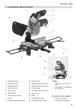
Parts Identification 
(standard delivery).................... 14

2.

Please Read First!..................... 15

3.

Safety ......................................... 15

3.1 Specified Conditions of Use........ 15

3.2 General Safety Instructions ........ 15

3.3 Symbols Used............................. 16

3.4 Safety Devices............................ 17

4.

Installation and Transport........ 17

5.

Special Product Features......... 18

6.

Machine Details......................... 18
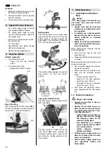
7.

Initial Operation ........................ 18

7.1 Installation of the Dust Bag......... 18

7.2 Mains Connection ....................... 18
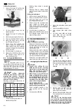
8.

Operation................................... 19

8.1 Standard Cross Cuts .................. 19

8.2 Mitre Cuts ................................... 19

8.3 Bevel Cuts .................................. 19

8.4 Compound Mitre Cuts................. 20
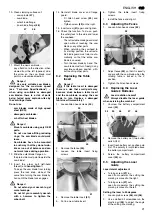
9.

Care and Maintenance.............. 20

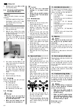
9.1 Changing the Saw Blade ............ 20

9.2 Replacing the Table Insert .......... 21

9.3 Adjusting the Fence .................... 21

9.4 Replacing the Laser Guide's 

Batteries...................................... 21

9.5 Adjusting the Laser Guide .......... 21

9.6 Checking and Replacing the 

Carbon Brushes .......................... 22

9.7 Cleaning...................................... 22

9.8 Storage ....................................... 22

9.9 Maintenance ............................... 22

10. Tips and Tricks ......................... 22

11. Available Accessories......... 22/48

12. Repairs....................................... 22

13. Environmental Protection ........ 22

14. Troubleshooting Guide ............ 22

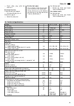
15. Technical Specifications.......... 23

15.1 Available Saw Blades ................. 24

These operating instructions have been
written to make it easier for you, the
user, to learn how to operate this
machine and to do so safely. These
instructions should be used as follows: 

Read these instructions before use.
Pay special attention to the safety
information.

These operating instructions are
intended for people with basic tech-
nical knowledge regarding the oper-
ation of a machine like the one
described in these instructions.
Inexperienced persons are strongly
advised to seek competent advise
and guidance from an experienced

person before operating this
machine. 

Keep all documents supplied with
this machine for future reference.
Retain your proof of purchase in
case of a future warranty claim. 

This machine must not be sold or
lent to someone else without being
accompanied by these operating
instructions and all other machine
documents.

The manufacturer assumes no liabil-
ity for any damage resulting from the
non-observance of any operating or
safety instructions given in this man-
ual. 

Information in these operating instruc-
tions is designated as under: 

Danger! 
Risk of personal injury or
environmental damage. 

Risk of electric shock! 
Risk of personal injury
by electric shock. 

Entanglement hazard! 
Risk of personal injury
by body parts or clothing
being drawn into the
rotating saw blade. 

Caution! 
Risk of material damage. 

Note:

Additional information. 

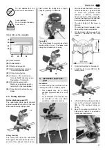
At times numbers are used in illus-
trations (

1

,

2

,

3

, ...). These number 

indicate component parts; 

are consecutively numbered; 

correspond with the number(s) in
brackets 

(1)

,

(2)

,

(3)

 ... in the

neighbouring text. 

Numbered steps must be carried out
in sequence. 

Instructions which can be carried
out in any order are indicated by a
bullet point (•). 

Listings are indicated by a dash (–). 

3.1

Specified Conditions of 
Use

This machine is intended for rip cuts and
cross cuts. Work only materials suitable
for cutting by the saw blade fitted (see
"Technical Specifications" for available
saw blades). 

Do not cut work pieces unless they con-
form to the permissible dimensions (see
chapter "Operation"). 

Do not cut pieces having an irregular
cross section, such as firewood,
because such pieces cannot be held
securely during cutting. A suitable auxil-
iary fence must be used when cutting
thin work pieces in an upright position. 

Any use other then the use specified
above, any alteration of the machine or
use of spare parts not tested and
approved by the manufacturer may
cause unforeseeable damage! 

3.2

General Safety Instruc-
tions 

x

When using this machine observe
the following safety instructions, to
minimize the risk of personal injury
or material damage. 

x

Please also observe the special
safety instructions given in the
respective chapters. 

x

Where applicable, follow the legal
directives or regulations for the pre-
vention of accidents pertaining to
the use of crosscut saws. 

A

General Danger! 

x

Keep your work area tidy – a messy
work area invites accidents. 

x

Be alert. Know what you are doing.
Set out to work with reason. Do not
operate the machine while under the
influence of drugs, alcohol or medi-
cation.

x

Consider environmental conditions:
keep work area well lighted. 

x

Prevent adverse body positions.
Ensure firm footing and keep your
balance at all times. 

x

Do not operate the machine near
inflammable liquids or gases. 

x

This machine shall only be operated
by persons familiar with crosscut
saws, their operation and the spe-
cific risks associated with the opera-
tion of crosscut saws. 
Persons under 18 years of age shall
use this machine only in the course
of their vocational training, under the
supervision of an instructor. 

x

Keep bystanders, particularly chil-
dren, out of the danger zone. Do not
permit other persons to touch the
machine or power cable while it is
running. 

x

Do not overload the machine – see
chapter 15, "Technical Specifica-
tions", for more information on the
performance range and limitations
of this machine. 

Table of Contents

2.

Please Read First! 

3.

Safety 

Summary of Contents for KS 210 Lasercut

Page 1: ...115 172 2080 4507 1 3 KS 210 Lasercut Betriebsanleitung 3 Operating Instructions 14 Instructions d utilisation 25 Manuale d istruzioni 37 A0375IVZ_13 fm...

Page 2: ...p eget ansvar att denna produkt verensst mmer med f ljande standarder enligt best mmelserna i direktiven FIN SUOMI NO NORGE VAATIMUKSENMUKAISUUSVAKUUTUS SAMSVARSERKL RING Vakuutamme ett t m tuote vast...

Page 3: ...Tisch 9 Feststellschraube f r Drehtisch 10 Drehtisch 11 Werkst ckspannvorrichtung 12 Ein Aus Schalter Laser 13 Staubbeutel 14 Ein Aus Schalter der S ge 15 S gekopf 16 Motor 17 Transport Arretierung 1...

Page 4: ...3 kennzeichnen Einzelteile sind fortlaufend durchnumme riert beziehen sich auf entspre chende Zahlen in Klammern 1 2 3 im benachbarten Text Handlungsanweisungen bei denen die Reihenfolge beachtet wer...

Page 5: ...S gen Sie niemals mehrere Werk st cke gleichzeitig auch keine B ndel die aus mehreren Einzelst cken bestehen Es besteht Unfallge fahr wenn einzelne St cke unkon trolliert vom S geblatt erfasst werden...

Page 6: ...die bewegliche S geblattabdeckung das S geblatt bleibt abgedeckt und die Kapps ge kann nicht abgesenkt werden solange die Sicherheits Verriegelung nicht zur Seite geschwenkt ist Werkst ckanschlag 29 D...

Page 7: ...schalten Ein Aus Schalter dr cken x Motor ausschalten Ein Aus Schalter loslassen Neigungseinstellung Nach L sen der Feststellschraube 33 auf der R ckseite kann die S ge stufen los zwischen 0 und 45 zu...

Page 8: ...n Sie beim S gen die rich tige Arbeitsposition ein vorn an der Bedienerseite frontal zur S ge neben der S geblattflucht x Quetschgefahr Greifen Sie beim Neigen oder Schwenken des S gekopfes nicht in d...

Page 9: ...s gen 9 Ein Aus Schalter loslassen und S gekopf langsam in obere Aus gangsstellung zur ckschwenken lassen 8 4 Doppelgehrungsschnitte 3 Hinweis Der Doppelgehrungsschnitt ist eine Kombination aus Gehrun...

Page 10: ...eeignete S gebl tter die f r die maximale Drehzahl ausgelegt sind siehe Technische Daten bei ungeeigne ten oder besch digten S gebl ttern k nnen durch die Fliehkraft Teile explosionsartig weggeschleud...

Page 11: ...den Winkel der Anriss Linie einstellen 3 Madenschrauben 56 und 58 fest ziehen um die Einstellung zu sichern 9 6 Kohleb rsten pr fen und austauschen 3 Hinweis Verschlissene Kohleb rsten machen sich bem...

Page 12: ...ktrowerk zeugen d rfen nur durch eine Elektro fachkraft ausgef hrt werden Reparaturbed rftige Elektrowerkzeuge k nnen an die Service Niederlassung Ihres Landes eingesandt werden Die Adresse finden Sie...

Page 13: ...etriebsbereit kg kg 10 5 9 0 Zul ssige Betriebsumgebungstemperatur Zul ssige Transport und Lagertemperatur C C 0 40 0 40 Ger uschemission nach EN ISO 3744 Schallleistungspegel LWA Schalldruckpegel am...

Page 14: ...e side extension 8 Saw base 9 Rotating table lock screw 10 Rotating table 11 Work clamp 12 Laser ON OFF switch 13 Dust bag 14 Saw ON OFF switch 15 Sawhead 16 Motor 17 Transport lock 18 Lock screw for...

Page 15: ...times numbers are used in illus trations 1 2 3 These number indicate component parts are consecutively numbered correspond with the number s in brackets 1 2 3 in the neighbouring text Numbered steps...

Page 16: ...ntain ropes strings cords cables or wires or to which any of the above are attached A Hazard generated by insuffi cient personal protection gear x Wear ear protection x Wear safety goggles x Wear dust...

Page 17: ...ine can be screw fastened to a plywood sheet or wood core plywood sheet 500 mm x 500 mm thickness 19 mm minimum When using the machine the sheet must be attached to a work bench with G clamps The idea...

Page 18: ...ay cause cancer when inhaled x Always work with the dust bag installed or a suitable dust collec tor connected x In addition use a dust respirator because the saw dust is not com pletely collected or...

Page 19: ...ly down holding the handle firmly When sawing exert only moderate pressure to prevent the motor speed to drop too much 5 Cut work piece in a single pass 6 Release the ON OFF switch and let the sawhead...

Page 20: ...wly return to its upper starting position A Danger Unplug before servicing Repair and maintenance work other than described in this section should only be performed by trained and qualified personnel...

Page 21: ...r any other parts When returning the sawhead to its starting position the retracta ble blade guard must return auto matically so that the entire saw blade is covered Turn the saw blade by hand The saw...

Page 22: ...saw When performing bevel cuts hold the work piece on the right side of the saw blade When making cuts that will result in small cutoffs use an auxiliary fence this may be a suitable wooden board fix...

Page 23: ...mm 430 x 355 x 350 460 x 390 x 485 430 x 355 x 350 460 x 390 x 485 Maximum work piece cross section Standard cross cuts width height Mitre cuts rotating table 45 width height Bevel cuts sawhead tilte...

Page 24: ...teeth Used for Stock no 210 mm 30 mm 24 alternate top bevel teeth wood 091 005 8843 210 mm 30 mm 40 alternate top bevel teeth wood non lamintated particle board 091 005 1148 210 mm 30 mm 64 flat trape...

Page 25: ...ble tournante 10 Table tournante 11 Dispositif de serrage de la pi ce 12 Interrupteur marche arr t du laser 13 Sac poussi res 14 Interrupteur marche arr t de la 15 T te de la scie 16 Moteur 17 Verroui...

Page 26: ...n Risque d accrochage Risque de l sions corpo relles pouvant tre occa sionn es par accro chage de parties du corps ou de v tements Attention Risque de dommages mat riels Remarque Informations compl me...

Page 27: ...s Si une dent de scie mouss e se coince dans la surface de la pi ce le danger de rebond est encore plus lev x Ne coincez pas les pi ces x Pour r aliser des rainures vitez d appuyer lat ralement sur la...

Page 28: ...sez pas l appareil dans un environnement mouill ou humide Rayon laser Ne pas regarder le rayon Classe de laser 2 Indications sur la plaque signal ti que 3 4 Dispositifs de s curit Protection mobile de...

Page 29: ...ever l appareil par la poign e Plage d angle de coupe de 45q pour les coupes obliques vers la gauche Plage d angle de coupe de 92q pour les coupes d onglet de 46q gau che 46q droite avec neuf posi tio...

Page 30: ...eur des liquides agressifs et des ar tes tranchantes x Utilisez comme rallonge unique ment des c bles gaine en caout chouc de section suffisante 3 x 1 5 mm2 x Ne tirez pas sur le c ble pour d brancher...

Page 31: ...40 de l inclinaison l arri re de la scie 2 Inclinez lentement le bras basculant jusqu la position souhait e 3 Fixez la vis de blocage de l inclinai son 4 Appuyez la pi ce contre la but e de pi ce 5 Ap...

Page 32: ...tion mobile de la lame de scie 43 4 Desserrer la vis droite 42 5 D visser compl tement la vis six pans creux 45 6 Soulever la protection de la lame de scie 43 et la protection de bride 44 et placer la...

Page 33: ...z les vis six pans creux 52 2 Placez la but e de pi ce 53 de mani re ce qu elle soit rigoureuse ment angle droit par rapport la lame de scie lorsque la table tour nante se bloque en position 0 3 Serre...

Page 34: ...aces des tables d appui liminez en particu lier les restes de r sine l aide d un spray de nettoyage et de mainte nance appropri Pour les travaux particuliers vous trou verez les accessoires suivants c...

Page 35: ...ion maximale de la pi ce Coupes rectilignes Largeur Hauteur Coupes d onglet table tournante 45 Largeur Hauteur Coupes inclin es bras basculant 45 gauche Largeur Hauteur Coupe d onglet double table tou...

Page 36: ...ts Utilisation N d art 210 mm 30 mm 24 dents biseaux altern s Bois 091 005 8843 210 mm 30 mm 40 dents biseaux altern s Bois panneaux de particu les non m lamin s 091 005 1148 210 mm 30 mm 64 dents pla...

Page 37: ...o girevole 10 Piano girevole 11 Tenditore per pezzi 12 Interruttore di accensione spegni mento del laser 13 Sacchetto raccoglipolvere 14 Interruttore di accensione spegni 15 Gruppo sega 16 Motore 17 A...

Page 38: ...indumenti impigliati Attenzione Avvertenza per possibili danni materiali Nota Informazioni integrative I numeri nelle figure 1 2 3 ecc indicano i singoli pezzi usano una numerazione progres siva si ri...

Page 39: ...ne delle scanala ture evitare la pressione laterale sulla lama utilizzare un dispositivo di blocco x In caso di dubbio controllare l even tuale presenza di corpi estranei ad esempio chiodi oppure viti...

Page 40: ...hetta del modello 3 4 Dispositivi di sicurezza Copertura mobile della lama della sega 27 La copertura mobile della lama della sega protegge l operatore da contatti involontari con la lama della sega e...

Page 41: ...arec chio 3 Sollevare l apparecchio dalla mani glia di trasporto Area dell angolo di taglio per tagli con inclinazione a sinistra di 45q Area dell angolo di taglio per tagli inclinati da 46q a sinistr...

Page 42: ...entare e controllata x Posizionare il cavo di alimenta zione in modo che non interferi sca col lavoro e che non possa subire danni x Proteggere il cavo di alimenta zione da calore fluidi aggressivi e...

Page 43: ...45 Posizione di partenza Arresto per il trasporto estratto Gruppo sega orientato verso l alto Piano girevole in posizione 0 vite di arresto del piano girevole serrata Come segare il pezzo 1 Allentare...

Page 44: ...guanti per sostituire le lame x Pericolo per il raggio laser Durante gli interventi di manuten zione spegnere sempre il laser di taglio 1 Bloccare il gruppo sega in posizione superiore con la protezi...

Page 45: ...a esagonale incassata 52 2 Regolare la battuta 53 in modo tale che risulti esattamente perpendico lare alla lama della sega quando il piano girevole si trova nella posi zione a 0 3 Fissare le viti a t...

Page 46: ...no disponibili gli acces sori riportati di seguito Le rispettive figure sono riportate sulla pagina di copertina posteriore A Lama della sega rivestita in metallo duro 210 x 1 8 1 4 x 30 24 W per il t...

Page 47: ...di imballaggio Apparecchio pronto all uso kg kg 10 5 9 0 Condizioni dell ambiente operativo Temperatura di trasporto e immagazzinaggio C C 0 40 0 40 Emissione di rumori in base a EN ISO 3744 Livello d...

Page 48: ...5 9823 HW 210 x 1 8 1 4 x 30 24 W HW 210 x 2 4 1 8 x 30 40 W HW 210 x 2 4 1 6 x 30 64 FT U3A0375 fm www metabo com Metabowerke GmbH Werk Meppen Daimlerstra e 1 D 49716 Meppen ZINDEL AG Technische Doku...

Reviews: