background image

ENGLISH

en

8

Additional Warnings:

California Prop 65 08_2018

Some dust created by power 

sanding, sawing, grinding, 

drilling, and other construction activities 

contains chemicals known to cause cancer, 

birth defects or other reproductive harm. Some 

examples of these chemicals are:

• Lead from lead-based paints,

• Crystalline silica from bricks and cement and 

other masonry products, and

• Arsenic and chromium from chemicallytreated 

lumber.

Your risk from these exposures varies, depending 

on how often you do this type of work. To reduce 

your exposure to these chemicals: work in a well 

ventilated area, and work with approved safety 

equipment, such as those dust masks that are 

specially designed to filter out microscopic 

particles.
SYMBOLS ON THE TOOLS:

......... Class II Construction 

V............. volts 

A............. amperes 

Hz........... hertz

.../min ..... revolutions per minute

rpm ......... revolutions per minute

~ ............. alternating current

............ alternating current /direct current

n ............. rated speed

See page 2.

1 Spindle locking button

2 Sliding on/off switch

3 Handle

4 Speed adjustment wheel

5 Electronic signal indicator *

6 Dust  filter  *

7 Bar auxiliary handle *

8 Thumb screws of the bar auxiliary handle *

9 Locking discs of the bar auxiliary handle *

10 Threaded holes on gear housing

11 Additional handle *

12 Lock button 

13 Trigger
* depending on equipment/not in scope of delivery

Before commissioning, check that the rated 

mains voltage and mains frequency, as stated 

on the type plate match your power supply.

Always install an RCD/GFCI with a maximum 

trip current of 30 mA upstream.
Always guide the angle polisher with both 

hands on the handles provided.

5.1 PE 15-20 RT: Attaching the additional 

handle

Always work with the auxiliary handle (11) 

attached! Attach the auxiliary handle on the 

left or right of the machine and secure.

5.2 PE 15-30: Fitting of bar auxiliary handle

Always work with the bar auxiliary handle (7) 

attached! Fit the bar auxiliary handle as shown 

(see illustration A, page 2).
- Fit locking discs (9) to the left and right of the gear 

housing.

- Fit the bar auxiliary handle (7) at the gear housing.

- Insert the thumb screws (8) left and right into the 

bar auxiliary handle (7) and turn gently.

- Adjust the bar auxiliary handle (7) to the required 

angle.

- Firmly tighten the thumb screws (8) to the left and 

right manually.

5.3 Dust filter (depending on features)

Assembly see page 2, fig. B.

Regularly clean the dust filter. See chapter 8. 

Cleaning.

Press in the spindle locking knob (1) only 

when the spindle is stationary!

Locking the spindle

Press in the spindle locking button (1) and turn the 

spindle by hand until the spindle locking button 

engages.

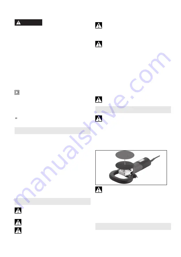
6.1 Installing support plate and sanding 

sheet

Only use the adjusting nut supplied with the 

support plate.

Place the support plate on the spindle as shown in 

the illustration. Screw on sanding sheet with 

adjusting nut supplied with support plate. Lock the 

spindle. Tighten sanding sheet with support plate 

manually in a clockwise direction. 
Release by hand or with a two-hole spanner if 

necessary.

7.1 Setting speed

The speed can be preset via the thumb-wheel (4) 

and is infinitely variable. 

4. Overview

5. Initial Operation

WARNING

6. Installing the tools

7. Use

Summary of Contents for PE 15-20 RT

Page 1: ...www metabo com Made in Germany PE 15 20 RT PE 15 30 en Operating instructions 5 fr Mode d emploi 11 es Instrucciones de manejo 18...

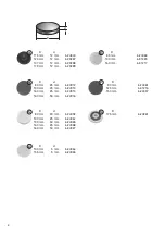
Page 2: ...13 3 1 2 3 4 5 6 1 11 12 4 6 8 9 10 7 A B PE 15 25 B PE 15 20 RT 2...

Page 3: ...5 1600 10 6 1900 10 1 800 10 2 1250 10 3 1700 10 4 2150 10 5 2600 10 6 3000 10 nN min 1 rpm 1720 2810 I120V A 13 13 P1 W 1500 1500 P2 W 1000 850 m Ibs kg 5 3 2 4 5 3 2 4 ah DS Kh DS m s2 1 6 1 5 3 5 1...

Page 4: ...5 mm 6 24965 C D d 80 mm 20 mm 6 24092 130 mm 25 mm 6 24967 130 mm 50 mm 6 24926 160 mm 25 mm 6 24968 160 mm 50 mm 6 24927 B D d 80 mm 25 mm 6 24912 130 mm 25 mm 6 24913 160 mm 25 mm 6 24915 160 mm 5...

Page 5: ...k of electric shock d Do not abuse the cord Never use the cord for carrying pulling or unplugging the power tool Keep cord away from heat oil sharp edges or moving parts Damaged or entangled cords inc...

Page 6: ...external diameter and thickness of your accessory must be within the capacity rating of your power tool Incorrectly sized accessories cannot be adequately guarded or controlled f Threaded mounting of...

Page 7: ...sized sanding disc paper Follow manufacturers recommendations when selecting sanding paper Larger sanding paper extending beyond the sanding pad presents a laceration hazard and may cause snagging tea...

Page 8: ...h a maximum trip current of 30 mA upstream Always guide the angle polisher with both hands on the handles provided 5 1 PE 15 20 RT Attaching the additional handle Always work with the auxiliary handle...

Page 9: ...Press down the machine evenly on the surface and move back and forth so that the surface of the workpiece does not become too hot It is possible that particles deposit inside the power tool during ope...

Page 10: ...d I120 V Current at 120 V nS No load speed depending on the thumb wheel position nN Speed at rated load P1 Rated input power P2 Power output m Weight without mains cable Energy rich high frequency int...

Page 11: ...ectrique a Il faut que les fiches de l outil lectrique soient adapt es au socle Ne jamais modifier la fiche de quelque fa on que ce soit Ne pas utiliser d adaptateurs avec des outils branchement de te...

Page 12: ...er et sont plus faciles contr ler g Utiliser l outil les accessoires et les lames etc conform ment ces instructions en tenant compte des conditions de travail et du travail r aliser L utilisation de l...

Page 13: ...de percer votre corps n Nettoyer r guli rement les orifices d a ration de votre outil lectrique Le ventilateur du moteur attirera les poussi res l int rieur du bo tier et une accumulation excessive d...

Page 14: ...ujours monter un interrupteur de protection contre les courants de court circuit RCD avec un courant de d clenchement max de 30 mA en amont Lorsque la machine est arr t e par son interrupteur de prote...

Page 15: ...si res Voir chapitre 8 Nettoyage N enfoncer le bouton de blocage de la broche 1 qu condition que la broche soit l arr t Blocage de la broche Enfoncez le bouton de blocage de la broche 1 et tournez la...

Page 16: ...d p ts de poussi re trop importants sur le filtre poussi res r duisent le refroidissement du moteur le moteur risque de surchauffer et d tre endommag Nettoyez r guli rement souvent et soigneusement le...

Page 17: ...cessent d s la disparition des perturbations Les caract ristiques techniques indiqu es sont soumises tol rance selon les normes en vigueur correspondantes Valeurs d mission Ces valeurs permettent l e...

Page 18: ...trica a El enchufe de la herramienta el ctrica debe corresponder a la toma de corriente utilizada No es admisible modificar el enchufe en forma alguna No emplee adaptadores con herramientas el ctricas...

Page 19: ...existen partes rotas o deterioradas que pudieran afectar a su funcionamiento Si la herramienta el ctrica estuviese defectuosa h gala reparar antes de volver a utilizarla Muchos de los accidentes se de...

Page 20: ...movimiento Si pierde el control sobre la herramienta el cable de alimentaci n puede cortarse o engancharse y su mano o su brazo pueden terminar en la herramienta de inserci n en movimiento I Nunca dep...

Page 21: ...mientas con inserci n roscada el extremo del husillo no debe tocar el fondo del orificio de la herramienta de lijado Compruebe que la rosca de las herramientas de inserci n sea lo suficientemente larg...

Page 22: ...rcasa de engranaje Insertar los tornillos de mariposa 8 a la derecha y a la izquierda de la empu adura de estribo complementaria 7 y apretar ligeramente Ajustar el ngulo deseado en la empu adura de es...

Page 23: ...5 20 RT Presione la herramienta con fuerza moderada y despl cela sobre la superficie a uno y otro lado para que la superficie de la pieza de trabajo no se caliente en exceso Durante el mecanizado pued...

Page 24: ...en funci n de las innovaciones tecnol gicas Dm x di metro m ximo de la placa de apoyo Mt m x m x par de giro M Rosca del husillo l Longitud del husillo de lijado n N mero de revoluciones de marcha en...

Page 25: ......

Page 26: ......

Page 27: ......

Page 28: ...Metabowerke GmbH Metabo Allee 1 72622 Nuertingen Germany www metabo com 170 27 508 0319...

Reviews: