background image

OPERATION

Proper Use

The jig saw is designed for sawing non-ferrous
metals and sheet steel, wood and similar materi-
als, and plastics and similar materials. Use for
any other purpose is prohibited. The operator
bears sole responsibility for any damage caused
by inappropriate use. The generally recognized
accident prevention regulations and the accom-
panying safety instructions must be observed.

Special Safety Instructions

Before using the power tool, read the accompa-
nying Safety Instructions and these Operating
Instructions carefully and thoroughly. Keep all of
the documents supplied with the tool in a safe
place. Always wear safety goggles, ear protec-
tors, protective gloves and heavy-duty footwear
when working with your power tool.

Special Product Features

Recessed blade-support roller with guide groove
to ensure accurate cutting. 5-position adjustable
orbital saw-blade movement to ensure high cut-
ting performance. Hard-wearing die-cast alu-
minum casing with good heat dissipation proper-
ties to protect against overheating

Initial Use

Before initial use, check that the voltage stated
on the rating plate matches the figures for your
electrical supply.

Do not run the tool without a saw blade fitted.

Remove the plug from the electrical outlet before
changing a saw blade.

Inserting the jig-saw blade

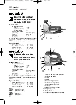
STE 135 Plus, STEB 135 Plus:

Push the safety guard (6) upwards or remove
the guard cover (8), as appropriate. Separate the
guard cover (8) at the ribbing and remove the
guard cover (8) from the front. Turn the clamping
lever on the rapid-change clamping device (7) all
the way around. Push the saw blade (10) fully
home into the rapid-change clamping device (7).
The saw blade must be properly seated in the
grooved blade-support roller. Release the clamp-
ing lever.

STE 135, STEB 135:

Push the guard cover (8) upwards. Slacken off
the hexagonal socket-head screw. Push the saw
blade (10) fully home into the saw-blade clamp-
ing device (7). The saw blade must be properly
seated in the grooved blade-support roller.
Retighten the hexagonal socket-head screw.

Switching on and off

STE 135 Plus:

Switching on: Push the slide-switch (4) forward.
Switching off: Press the rear of the slide-switch
(4). The slide-switch (4) is released and springs
backward.

STEB 135 Plus:

Press the switch trigger (3).For continuous oper-
ation press the switch trigger (3) in fully and hold
down. Press the locking button (2) in and hold
down.Release the switch trigger (3) and then the
locking button (2), in that order.To release, press
the switch trigger (3) in fully and release. 

Fitting the anti-splintering foot-plate 

Insert the anti-splintering foot-plate insert (9) fully
into the foot-plate (11).

Speed Setting

The variable speed setting (1) adjusts the speed
infinitely from 1000 to 3000 strokes/minute.
Generally soft woods, plywoods, and particle-
board are run on 6. Plastics, PVC, Plexiglas set
dial to 3-5, soft metals (i.e. copper, aluminum) 
3-5, ferrous metals on 3-4.

Orbital setting

The orbital setting adjusts the rake of the blade.
O disables any forward rake, with 1-4 increasing
the forward rake of the blade. A greater rake will
increase the cut speed but cause a rougher cut.
Generally, soft woods, plywood use setting 0-5.
Particle board, plastics 0-3, soft metals (copper,
aluminum) 0-1, ferrous metals 0.

Sawdust extraction

For optimum vacuum extraction results, use in
conjunction with the guard cover (8). For saw-
dust extraction, connect up a suitable vacuum
cleaner to the chip-extraction nozzle (12).

Fitting the chip-extraction nozzle

Push the chip-extraction nozzle (12) fully home.

Removing the chip-extraction nozzle

Pull the chip-extraction nozzle (12) out of its
seating.

Sawing without sawdust extraction

Remove the guard cover (8). Flip down the safe-
ty guard (6).

Sawing in a restricted space

Remove the guard cover (8) and the anti-splin-
tering foot-plate insert (9). Loosen the socket-
head screw in the center of the foot-plate (11)
and slide the foot-plate backward until seated.
Retighten the hexagonal socket-head screw. 

Bevel cuts

Remove the guard cover (8), the anti-splintering
foot-plate insert (9) and the chip-extraction noz-
zle (12). Loosen the socket-head screw in the
foot-plate (11). Slide the foot-plate (11) forward,
twist round and push backwards into the appro-
priate notches. Retighten the socket-screw (16).
The angle set can be read off from the number
on the foot-plate base. Preset bevel angles of
15

o

, 30

o

and 45

o

are achieved by engaging the

relevant notches. For very exact bevel cuts, first
carry out a test cut and check with a protractor.

5

ENGLISH

STE/STEB 135 Plus NAFTA  18.12.2007  11:41 Uhr  Seite 5

Summary of Contents for STE 135 -

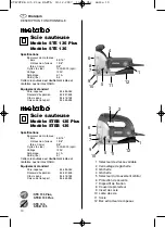
Page 1: ...do na Alemanha STE 135 Plus STE 135 STEB 135 Plus STEB 135 170 24 8960 0108 Instructions for use page 2 17 Mode d emploi pages pages 8 13 Instrucciones de manejo p gina 14 19 Instru es de servi io p g...

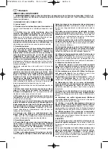
Page 2: ...structions listed below may result in electric shock fire and or serious personal injury SAVE THESE INSTRUCTIONS 2 Work Area 2 1 Keep your work area clean and well lit Cluttered benches and dark areas...

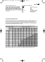
Page 3: ...ensions for Portable Electric Tools Gage sizes in shaded areas are normally not available as flexible extension cords USE PROPER EXTENSION CORD Make sure your extension cord is in good condition When...

Page 4: ...ferrous metals 1 3 8 sheet steel 3 8 Stroke rate no load 1000 3000 spm Voltage 120V Amperage 6 1 A Weight lbs 5 7 This jig saw is of approved double insulated con struction and complies with OSHA Sta...

Page 5: ...4 The slide switch 4 is released and springs backward STEB 135 Plus Press the switch trigger 3 For continuous oper ation press the switch trigger 3 in fully and hold down Press the locking button 2 i...

Page 6: ...ched on again after being switched off Servicing Each time the carbon brushes need replacement the jig saw should be thoroughly inspected and the motor cleaned This work should only be done by skilled...

Page 7: ...7 STE STEB 135 Plus NAFTA 18 12 2007 11 41 Uhr Seite 7...

Page 8: ...e blessures DIRECTIVES DE S CURIT 1 AVERTISSEMENT Lisez toutes les directives et assurez vous de bien les comprendre N gliger de suivre les directives mentionn es ci dessous pourrait entra ner des ris...

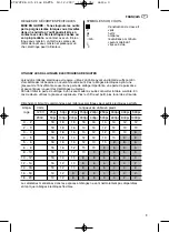
Page 9: ...ue rallonges lectriques flexibles UTILISEZ LES RALLONGES ELECTRIQUES AD QUATES Lorsqu une rallonge lectrique est requise utilisez un c ble ayant un diam tre suffisant afin d accommoder les besoins en...

Page 10: ...8 t le en acier 3 8 Cycles vide 1000 3000 spm Voltage 120V Amp rage 6 1 A Poids lbs 5 7 Cette scie sauteuse est doublement isol e et conforme aux normes OSHA quipement standard Pare copeaux 34 435 04...

Page 11: ...rage de la lame 7 La lame de scie doit tre exactement positionn e dans la gorge du galet d appui Resserrer fond la vis six pans creux Mise en marche et arr t STE 135 Plus Mise en marche Poussez la gli...

Page 12: ...e support de la lame de scie tel que requis De temps autre lubrifiez le galet avec une goutte d huile Faites remplacer les balais en carbone par Metabo ou par un centre de service autoris Metabo BALAI...

Page 13: ...13 STE STEB 135 Plus NAFTA 18 12 2007 11 41 Uhr Seite 13...

Page 14: ...as m s adelante existe peligro de choques el ctricos fuego y graves lesiones personales GUARDE ESTAS INSTRUCCIONES 2 Puesto de trabajo 2 1 Mantenga limpio y bien iluminado su puesto de trabajo Los ban...

Page 15: ...1 m 400 Ft 121 m 500Ft 152 m 600 Ft 182 m 800Ft 243 m 1000 Ft 304 m AWG 18 0 82 mm2 AWG 16 1 31 mm2 AWG 14 2 08 mm2 AWG 12 3 31 mm2 AWG 10 5 26 mm2 AWG 8 8 37 mm2 UTILIZAR UN CABLE DE EXTENSION ADECUA...

Page 16: ...icos 1 3 8 chapa de acero 3 8 N mero de carreras en vac o 1000 3000 rpm Tensi n 120V CA Amperaje 6 1 A Peso lbs 5 7 Esta sierra de calar est construida con un doble aislamiento aprobado y cumpliendo l...

Page 17: ...gono interior Introducir la hoja de la sierra de calar 10 hasta el tope en el dispositivo de sujeci n 7 La hoja de sierra de calar debe quedar colocada correctamente en la ranura de la ruedecilla de...

Page 18: ...lesiones cortantes Todos los trabajos de mantenimiento deben ser llevados a cabo con la hoja de la sierra en reposo Desconectar la sierra de calar y desenchufar el cable de ali mentaci n del tomacorri...

Page 19: ...19 STE STEB 135 Plus NAFTA 18 12 2007 11 41 Uhr Seite 19...

Page 20: ...A GERAIS 1 ADVERT NCIA Ler e entender todas instru es A n o observa o destas instru es listadas abaixo pode causar choque el ctrico inc ndio e ou ferimentos graves GUARDAR ESTAS INSTRU ES COM CUIDADO...

Page 21: ...t 243 m 1000 Ft 304 m AWG 18 0 82 mm2 AWG 16 1 31 mm2 AWG 14 2 08 mm2 AWG 12 3 31 mm2 AWG 10 5 26 mm2 AWG 8 8 37 mm2 UTILIZAR O CABO EL CTRICO DE EXTENS O APROPRIADO Assegurar se que o cabo de extens...

Page 22: ...6 metais n o ferrosos 1 3 8 chapa de a o 3 8 Frequ ncia de golpes sem carga 1000 3000 spm Voltagem 120V Amperagem 6 1 A Peso lbs 5 7 Esta serra de recortes de constru o aprovada de isolamento duplo e...

Page 23: ...e encaixar na ranhura da roldana de apoio Apertar o parafuso de sextavado interno Ligar e desligar STE 135 Plus Ligar Empurrar o interruptor deslizante 4 para frente Desligar Pressionar a parte trasei...

Page 24: ...emover a ficha da tomada el ctri ca Limpar a abertura de entrada de ar atr s do rolo apoiando a serra de recortes como for necess rio Lubrificar o rolo periodicamente com uma gota de leo As escovas de...

Reviews: