background image


7

17

17

8

9

17

17

17

17

17

2

3

1

23

24

¡ ˘° ¢» ÁÕ ºÀ ˘  æ

£ ¨œ »≈ °ø ™

23∫ Õ

24£ ¨

          π” √  Æ

◊ ÷¬ ›À øµ ∂Ω ´8∫ Õ

9

        Õ ®π ˝23° ¢24∫ Õ

17À ¯Ω Ù

‘ ⁄2∫ Õ

3… œ

        ‘ Ÿ  π” √  Æ

◊ ÷¬ ›À øµ ∂Ω ´7Õ ®π ˝17

        À ¯Ω Ù

‘ ⁄1… œ

.

        ◊ Ó

∫ Û

◊ ∞

… œ

20£ ¨Ω ”… œ

µ Á‘ ¥œ fl.

20


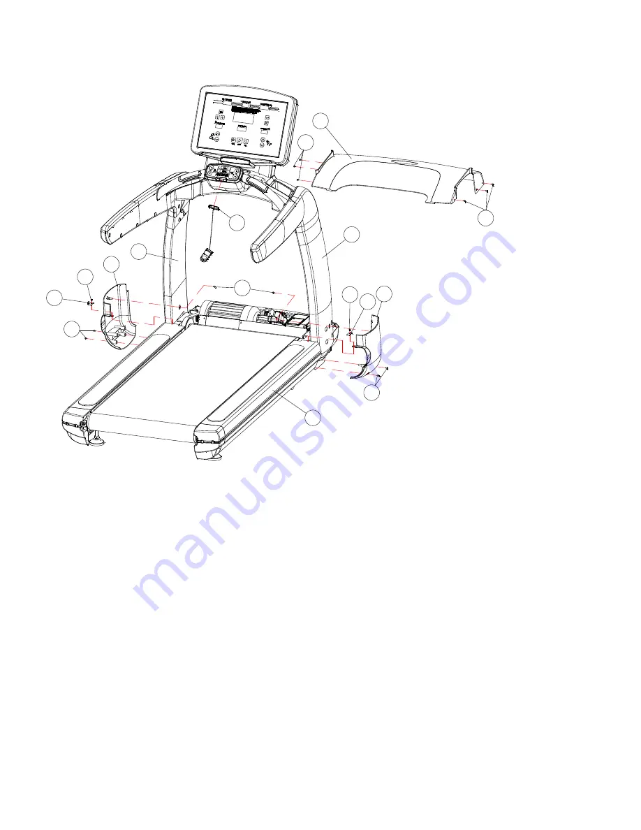
VI. As shown in the figure, firstly twist off part 23 and 24, use cross screwdriver to lock part 8 and 9 tightly 

onto 2 and 3 through 23,24 and 17, and then use cross screwdriver to lock part 7 lightly onto 1 through 17. At 

last install part 20, connect the power line.   


Please  notice:  You  can  only  connect  the  power  line  after  confirming  all  the  parts  are  installed  according  to  the 

instructions. 


Kindly reminder: Please check whether the security lock reset or not before starting the treadmill. 


Summary of Contents for MF-P096T

Page 1: ...T CO LTD INSTRUCTIONS OF INSTALLATION USE AND MAINTENANCE MANUAL NOTICE 1 Please read the manual carefully before using the electronic treadmill 2 Please keep the instruction well for future reference...

Page 2: ...e 0 40 Incline 0 20 degree SB Weight limit 180Kg Dashboard Time distance heart rate calorie speed incline Security 1 Red button on dashboard 2 PPTC 3 Circuit safety in the front of the dashboard Imple...

Page 3: ...6 6 Electrical meter 1 17 Cross self tapping screw ST4 15 14 7 Cover above motor 1 18 Flat gasket Dia 10 5 Dia 20 16 8 Side cover of right post 1 19 Flat gasket Dia 8 4 Dia 15 4 9 Side cover of left p...

Page 4: ...1 3 14 2 3 1 6 18 1 1 3 2 16 18 16 18 16 18 13 14 I As shown in the figure firstly connect part 13 and 14 and then use inner hexagon spanner to lock part 2 and 3 onto part 1 lightly through 16 and 18...

Page 5: ...1 13 12 1 2 13 5 1 6 18 2 3 5 II As shown in the figure firstly connect part 12 and 13 and then use inner hexagon spanner to lock part 5 onto part 2 and 3 lightly through 16 and 18 Then fasten the bo...

Page 6: ...6 4 1 5 19 5 5 4 15 19 15 19 III As shown in the figure use inner hexagon spanner to lock part 4 onto part 5 tightly through 15 and 19...

Page 7: ...7 22 22 IV As shown in the above figure open part 22 cross brace lower cover...

Page 8: ...into part 4 and connect part 11 with 12 A with a C with c D with d Then use inner hexagon spanner to lock part 6 onto 4 tightly through 15 At last cover part 22 cross brace lower cover AB C D b c a d...

Page 9: ...ightly onto 2 and 3 through 23 24 and 17 and then use cross screwdriver to lock part 7 lightly onto 1 through 17 At last install part 20 connect the power line Please notice You can only connect the p...

Page 10: ...ACC Power input AC15V 5 Operating temperature 20 60 Features l Dual core processing chip 1G RAM 4G NANDFLASH l High performance capacitive touch screen and Full view of the LCD screen Multi segment s...

Page 11: ...treadmill system will continue to operate to further enhance the system security and stability l Using multiple isolation protection technology completely solve the electromagnetic field to bring the...

Page 12: ...use the electric treadmill please be sure to put hands on handrails until adapting yourself to it 10 Please put the safety lock with a red thread on appropriate place in case of happening unexpectedly...

Reviews: