6
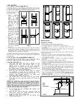
VARIABLE LENGTH
For installations that require non-standard vent lengths, Corr/Guard
Variable Length vent sections may be used. The vent section consists of
an inner conduit that slip fits into the outer conduit, a compression band,
or integral clamp and an outer casing for double wall only.
3”- 5” (76mm-127mm) CG & CGSW
To install the VL vent section, first install the inner pipe section by
connecting the male section to the adjoining double or single wall vent
pipe. Insert male section until the bead of the joint stops at the edge of
the female end of the vent section.
Next, expand the length of the inner pipe to the necessary length and
tighten the integral clamping band using a hex drive or screw driver. The
VL’s are adjustable from 7 1/2” to 22” (191mm to 559mm). Continue with
the next section of vent, making sure to fully join the inner pipe of the
vent from the female end of the VL vent.
When installing double wall, finish the VL vent assembly by installing the
outer casing wall around the VL inner pipe section. Secure the casing
by installing #8x1/2” sheet metal screws at prepunched holes (See
FIG.
14
).
FIG. 15
WARNING: Variable Length sections are not intended to be
subjected to vertical force loads. Use appropriate support
methods.
Supplementary support is required when installing offsets, elbows and
non-vertical runs to prevent unacceptable stresses. Do not allow vent to
sag or deflect from intended flow line during installation.
WARNING: Do not place any type of insulation in any required
clearance spaces surrounding this Vent System.
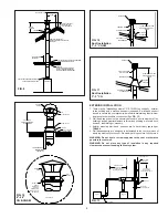
CONDENSATE DRAINS
If an appliance does not supply a condensate drain and one is required
per the appliance manufacturer’s instructions or local codes, install a
drain fitting in the horizontal conduit, as close as possible to the appli-
ance vent collar.
WARNING: NEVER INSTALL A DRAIN IN A SYSTEM WITH AN
APPLIANCE NOT INVESTIGATED FOR USE WITH A CONDENSATE
DRAIN.
Corr/Guard drain fittings contain a 1/2” (
13mm
) diameter drain tube that
should be located at the bottom of the vent or fitting when installed prop-
erly. A drain hose must be attached to the tube and a trap loop must be
formed into the drain hose. The trap loop should be at least four times the
appliance’s rated stack pressure in inches of water column or 6 inches
(
153mm
), whichever is less. (See
FIG. 16
)
When the Corr/Guard vent system is installed the system must be pres-
sure checked to for tightness. Repair any joint leaks by disassembling
and resealing following the guidelines in the Joint Assembly section of
these instructions. Replace any defective component.
The Corr/Guard ventilation system, manufactured by Metal-Fab, Inc..
is constructed to exacting standards. The proper operation of this vent
system is dependent on the use of correct components, proper sizing,
quality of installation, and guidelines and limitations expressed by the
appliance manufacturer.
TUBING
TRAP LooP
(4x STACK PRESSURE)
FIG. 16
6”- 24” (152mm-610mm) CG & CGSW
To install the VL, first apply a heavy bead of P077 Sealant into the inner
vent groove. Then slide the inner vent into the outer vent. Locate into
position and adjust to proper length. Follow Joint Assembly Details on
PAGES 2 & 3
. Apply a bead of P077 Sealant at the joint of inner and
outer vent and attach compression band. The 6” VL is adjustable from
7½” to 10” (191mm to 254mm) and the 12” (305mm) VL is adjustable
from 13½” to 22” (343mm to 559mm). When installing double wall, cut
outer jacket to fit between the mating vent and install using sheet metal
screws (supplied) (See
FIG 15
).
INNER FLUE
CASING JACKET
INTEGRAL CLAMP
FIG. 14
COMPRESSION
BAND
OUTER
JACKET
FOR CG
ONLY
GROOVE
OUTER CONDUIT
INNER CONDUIT
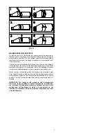
SMALL DIAMETER CGSW & CG TO CGSW & CG
Connections between vent and fittings are male / female type, sealed
with silicone sealant and secured with a profiled closure band. (See
FIG.
17
)
Connection Tips:
1. Clean male and female joint ends to remove oil and
contaminants with alcohol pads provided. Apply a ¼ inch
(
6.4mm
)
bead
of
sealant
to
the
male
connection
approximately ¼ inch (
6.4mm
) below the edge. Also apply ¼
inch (
6.4mm
) bead of sealant (approx. 2 inches long) along
the male joint at the overlap of the welded seam.
2.
Insert male end into female, twisting slightly, to ensure
even distribution of sealant. Be sure sections are seated.
Inspect the joint to ensure that vent gases will not escape.
If necessary, apply additional sealant to any visible voids
around the joint and smooth it into crevices.
3. Align profiled closure band snugly around the joint section.
Insert tongue into gear clamp and tighten with 3/8-inch hex
drive socket.
IMPORTANT: Profiled Vent connection band is formed to fit exactly
over the joint section. This part is not symmetrical and should be
installed in the proper orientation for maximum seal and support.
Allow sealant to cure for a minimum 24 hours before operating the
appliance. Any adhesives used in the assembly of the system are to
be used within their marked time limitations.
4. For CG (double wall) joint installations, first complete steps
1 thru 3 as shown above.
5. Once the inner vent joint has been connected, locate the
casing
band
around
the
casing,
positioning
the
band
between the formed beads on either casing.
6.
Tighten the band snugly around the vent casings using
3/8-inch hex drive socket.


