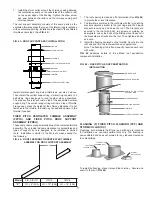
90º WYE (90Y)
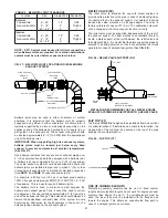
The 90º wye is very useful when the vertical chimney is located
between two appliances and a low-loss junction is desired. It is
ideal for engine with dual-exhaust connections. The wye fitting
may be suspended by a plate support or roof support assembly.
Expansion joints or bellows joints should be used to protect the
wye from thermal expansion stresses (See
FIG. 19
).
EXPANSION JOINT (AL)
The expansion joint may be used to compensate for thermal
expansion and to make up odd lengths. It is essential that
sufficient installed length be allowed to compensate for abnormal,
as well as normal, operating conditions. The expansion joint
cannot be used to correct misalignment or to compensate for
lateral movement or vibration. The use of the expansion joint in
engine exhaust applications is not recommended.
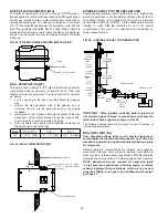
An expansion joint is comprised of: (1) a collar that is 5¼” (133)
long with a flange and vee band at one end and a graphite
impregnated ring gasket at the other; (2) a 30” (762) long tube,
flanged at one end, which fits into the 5¼” (133) collar; (3) an
outer jacket consisting of two half jacket assemblies; and (4)
loose insulation blanket to fill space between the tube and
casing.
Installation procedure is as follows:
1. Loosen draw screw at gasket band and slide collar toward
flanged end of tube. Do not remove collar from tube.
2. Slide unflanged end of tube into the upstream piece of pipe
and make up joint between pipe and collar following the
procedures outlined under heading JOINT ASSEMBLY on
Page 4.
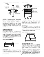
3. Pull flanged end of tube to the downstream piece of pipe and
make up joint as above (See
FIG. 20
).
4. For IPIC, cut insulation to desired length and wrap inner pipe
ensuring that it is covered completely before attaching half
jackets.
5. Wrap two half jackets around joint with bead at the
downstream end and punched edge overlapping plain edge
by approximate 3/4” (19).
NOTE:
For horizontal installations
the seams must be located at the top and bottom of the
pipe, coat unpunched edge of casing with P077 sealant to
waterproof the casing.
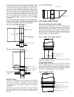
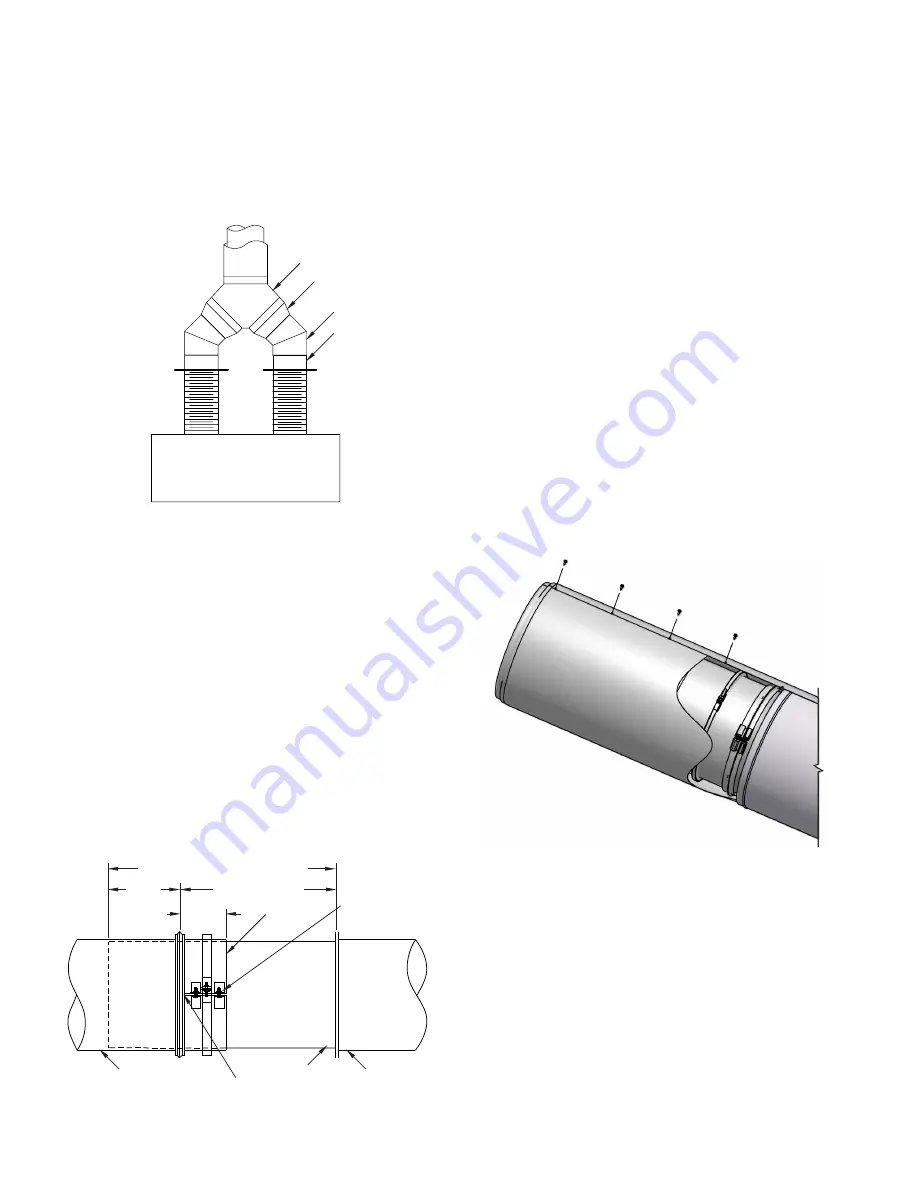
6. Install self-drilling screws (supplied with jacket) at punched
holed through both layers at overlap. Exercise care that half
jacket edges do not align with draw screws on flange bands
and that no screws are installed in portion of jacket which is
over casing of adjacent pieces of pipe (See
FIG. 21
). The
screws shipped with the expansion joint are of the correct
length to avoid penetrating the inner wall (flue) of the pipe.
Do not use any other screws to attach the casing.
FIG. 19 – 90º WYE APPLICATION, DUAL EXHAUST
ENGINE WITH
DUAL EXHAUSTS
90° WYE
TAPERED INCREASER
45° FIXED ELBOW
FLANGE ADAPTER
10
FIG. 21 - EXPANSION JOINT CASING ASSEMBLY
Note: Do not screw through casing of adjacent pipe.
FIG. 20 – EXPANSION JOINT FLUE ASSEMBLY
30” MAX. (762) OR TRIMMED AS REQ’D
8” MIN.
(203)
INSTALLED LENGTH
3-3/4”
(95)
COLLAR
PIPE
UNFLANGED END
RETAINING
SCREWS
ADJOINING PIPE
(UP SLOPE)
APPLY SEALANT
UNDER SEAM
(REF. JOINT ASSY. FOR
PROPER SEALANT)
ADJOINING PIPE
(DOWN SLOPE)


