background image

NOTES:

1.  It is recommended that the pipe on both sides of the 

expansion joint is supported or guided to assure that 

the expansion joint will not bind during operation.

2.  Installation  of  an  expansion  joint  adjacent  to  fittings, 

such as elbows, tees or wyes, is not recommended.  

However, it is not always possible to avoid these 

fittings.  If an expansion joint must be joined to one of 

these fittings, the unflanged end of the tube should be 

away from the fitting and fitted into a pipe length in the 

manner described in the installation procedure above.

3.  Expansion joint must be installed with a flange to flange 

length of not more than 22”. The minimum length for 

installation must take into account the amount of 

expansion that may occur during operation. Minimum 

length is calculated as follows:

Expansion = Length (feet)/100 x  Temperature Rise (ºF)/100
Minimum Length = Exp 6” (152mm)

It is recommended that the temperature used in the 

above formula be at least 300ºF higher than the expected 

normal operating temperature.

4.  If inner tube is too long, it may be cut to length. Tube 

must be a minimum of 8” (203) longer than flange-to-

flange length. Prior to installation of cut pipe, remove all 

burrs to ensure that interference does not occur.

5.  Check  gasket  to  ensure  that  it  fits  snugly  without 

binding on inner pipe.

6. Outer jacket must move during expansion or 

contraction. Ensure that no screws are located where 

the jacket overlaps the casing of the adjacent pipe and 

that it is loose enough to move as needed. Alignment 

of the bead on the jacket with the bead on the adjacent 

pipe will ensure that the jacket stays in the proper 

location.

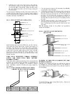
7.  Note that the expansion joint will not support any 

weight in the vertical position. It should not be used 

unless both ends of run, where an expansion joint is 

installed, are anchored as fixed points.
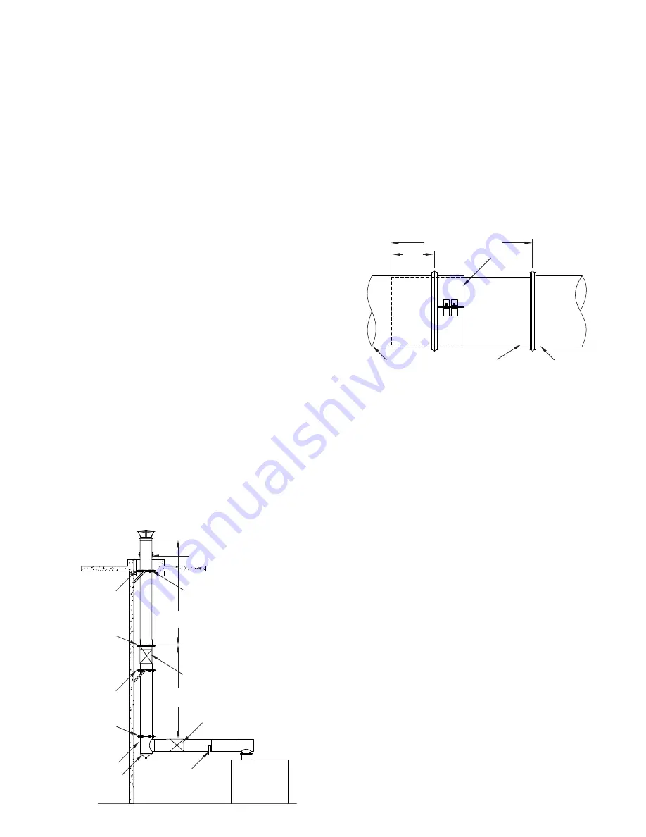
FIG. 22

 indicates appropriate locations for expansion joints in 

various orientations.

FIG. 22 – EXPANSION JOINT LOCATIONS

SEE TABLE 4 FOR 

MAXIMUM DISTANCE

SEE TABLE 4 FOR 

MAXIMUM DISTANCE

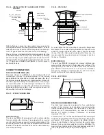
CHIMNEY EXPANSION UP THROUGH 

ROOF. GUIDANCE IS REQUIRED 

THROUGH FLASHING OR THIMBLE

EXPANSION JOINT  

ABSORBS UPWARD MOVEMENT

FLASHING

EXPANSION JOINT 

CAREFULLY ALIGNED

HALF OR FULL 

ANGLE RING

WALL GUIDE

WALL GUIDE

WALL OR PLATE 

SUPPORT

FIXED POINT 

PLATE SUPPORT

90° TEE

DRAIN TEE CAP

11

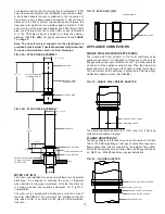
VARIABLE LENGTH (VL)

The function of the variable length is to make up odd lengths of 

pipe, which are not to be used for expansion compensation. The 

use of the variable length in engine exhaust applications is not 

recommended. The variable length is comprised of the following 

components: (1) a 3¼” (83) collar with a flange at one end used 

to clamp the flange at the desired length; (2) a 30” (762) long 

tube flanged at one end, which fits into the 3¼” (83) collar; (3) 

an outer jacket consisting of two half jacket assemblies; and (4) 

loose insulation blanket to fill space between the tube and casing.
A variable length can be installed at any flange to flange length 

from 4”-26” (102-660). If the flue is too long to fit into the adjacent 

section of pipe without interfering with the flow path, it should be 

trimmed to the desired flange to flange length plus 4” (102).

Installation procedure is as follows:

1.  Loosen draw screw at collar and slide collar toward flanged 

end of tube. Do not remove collar from tube.

2.  Slide unflanged end of tube into the upstream piece of pipe. 

Pull  flanged  end  of  tube  to  the  downstream  piece  of  pipe 

and make up joint as outlined under JOINT ASSEMBLY on 


Page 4.

3.  Apply a thin coat of sealant, about 1” (25) wide at the plain 

end of the pipe where tube slides into mating pipe section.  

Press sealant into any gap between the tube and the 

mating pipe section. Apply sealant to flange of mating pipe 


(See 

FIG. 23

).

4.  Slide collar into position against flange of mating pipe. Fill 

flange band with sealant and install flange band.  

5.  Tighten bolts on clamp collar to complete installation. (For 

more positive seal, apply sealant to clamp collar slot and 

flared end of collar prior to tightening bolts).

6.  For IPIC, cut insulation to desired length and wrap inner pipe 

ensuring that it is covered completely before attaching half 

jackets.

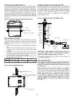
7.  Wrap  two  half  jackets  around  joint  with  bead  at  the 

downstream end and punched edge that overlapping the 

plain edge by approximately 3/4”. Note: For horizontal 

installations, the seams must be located at the top and 

bottom of the pipe. Coat unpunched edge of casing with 

P077 sealant to waterproof the casing. Install self-drilling 

screws (supplied with jacket) at punched holed through both 

layers at overlap. Exercise care that half jacket edges do not 

align with draw screws on flange bands, and that no screws 

are  installed  in  portion  of  jacket  which  is  over  casing  of 

adjacent pieces of pipe (See 

FIG. 24

). The screws shipped 

with the expansion joint are of the correct length to avoid 

penetrating the inner wall (flue) of the pipe. 

Do not use any other screws to attach the casing.

FIG. 23 VARIABLE LENGTH FLUE ASSEMBLY

TUBE

30” (762) OR TRIM TO FIT

4” MIN.  

(102)

UNFLANGED END

COLLAR

ADJOINING PIPE 

(DOWN STREAM)

ADJOINING PIPE 

(UP STREAM)

Summary of Contents for IPIC

Page 1: ...E INSTRUCTIONS VERY CAREFULLY Metal Fab s Model PIC IPIC Chimney has been fully tested and listed by Underwriters Laboratories Inc and Underwriters Laboratories of Canada Chimneys installed in accordance with these installation instructions will comply with national safety standards and building codes This booklet contains complete information on details concerning dimensions installation clearanc...

Page 2: ...tainless steels Complete system size and capacity information can be obtained from the ASHRAE Handbook Equipment Volume or by contacting Metal Fab Inc PO Box 1138 Wichita KS 67201 Refer to Metal Fab Model PIC IPIC Design Maual L1690 for description of all necessary components MULTI ENGINE EXHAUSTS NOT RECOMMENDED Where multiple engines are being considered it is recommended that they not be connec...

Page 3: ... or fully ventilated area on the same story as the appliance to which it is connected Model PIC IPIC Chimney shall be installed at a minimum of the clearance to combustibles as indicated in TABLE 1 Except for installation in one or two family dwellings a factory built chimney that extends through any zone above that on which the connected appliance is located is to be provided with an enclosure ha...

Page 4: ...etween inner and outer walls with insulation strips STEP 6 Secure the outer casing with the closure band When system is installed outdoors the upper side upper half in the horizontal position of the closure band bead should be sealed with P077 sealant to make the casing watertight JOINT ASSEMBLY The Model PIC IPIC joint sealing system is designed for quick and easy installation For most applicatio...

Page 5: ...m 17 6 5 33m 18 6 5 64m 20 0 6 10m 21 0 6 40m 22 0 6 71m 23 0 7 01m 24 0 7 32m 24 6 7 47m 25 0 7 62m 26 0 7 92m 27 0 8 23m 27 0 8 23m 28 6 8 69m 29 0 8 84m 30 0 9 14m 30 6 9 30m 31 0 9 45m 32 0 9 75m 32 6 9 91m 33 6 10 21m 34 6 10 52m 8 6 2 59m 8 9 2 67m 9 3 2 82m 10 0 3 05m 10 6 3 20m 11 0 3 35m 11 6 3 51m 12 0 3 66m 12 3 3 73m 12 6 3 81m 13 0 3 96m 13 6 4 11m 13 6 4 11m 14 3 4 34m 13 6 4 11m 15 ...

Page 6: ...on on the guy cables or braces a fixed point support plate or wall support assembly may be installed immediately below the roofline as shown in FIG 8 STORM COLLAR GUY RING HALF RINGS 4 PCS HALF CLOSURE BANDS 2 PCS FIG 5 PIC IPIC GUY RING EXPLODED VIEW FIG 4 FULL ANGLE RING FOR LATERAL SUPPORT CLOSURE RING STORM COLLAR FLASHING ROOF PIPE DIAMETER ANGLE RING MUST BE USED WITH FLASHING CHIMNEY ABOVE ...

Page 7: ...chimney The pipe flue is equipped with an annular catch ring and a 1 25 NPT nipple extending through the casing for attachment of drain piping The drain piping should include a water leg of a height at least equal to the maximum expected operating pressure at the appliance outlet to avoid allowing flue gases to vent through the drain Drain section should be installed indoors to prevent freezing Se...

Page 8: ...he next fixed support point the appliance outlet for example the tee should be protected from bending moments by use of an expansion joint or bellows joint See the sections on those fittings for additional information about compensation for thermal expansion FIG 12 SUSPENDED TEE PIPE RISER HALF CLOSURE BAND WALL SUPPORT ASSEMBLY HALF CLOSURE BAND TEE AT BASE OF RISER DRAIN TEE CAP PIPE SECTION Whe...

Page 9: ...hru 18 20 thru 30 32 thru 42 44 thru 48 6 152 7 3 4 197 7 3 4 197 8 1 2 216 11 279 12 3 4 324 9 7 8 251 14 1 8 359 14 1 2 368 16 5 8 422 19 3 4 503 23 3 4 602 Bracing above and below the elbows is needed to avoid subjecting them to bending moments In order for bracing to be effective it must be rigidly attached to building members or foundation The design of the structure used to attach supports m...

Page 10: ...nd make up joint between pipe and collar following the procedures outlined under heading JOINT ASSEMBLY on Page 4 3 Pull flanged end of tube to the downstream piece of pipe and make up joint as above See FIG 20 4 For IPIC cut insulation to desired length and wrap inner pipe ensuring that it is covered completely before attaching half jackets 5 Wrap two half jackets around joint with bead at the do...

Page 11: ...ansion compensation The use of the variable length in engine exhaust applications is not recommended The variable length is comprised of the following components 1 a 3 83 collar with a flange at one end used to clamp the flange at the desired length 2 a 30 762 long tube flanged at one end which fits into the 3 83 collar 3 an outer jacket consisting of two half jacket assemblies and 4 loose insulat...

Page 12: ...e the chimney to mis function and cause spillage of flue gases into the mechanical room The step increaser should be used when the length of run available for the size change is restricted The installed length of a step increaser is 2 51 See FIG 25 The step increaser is a non structural part and must not be subjected to loading in either the axial or lateral directions FIG 24 VARIABLE LENGTH CASIN...

Page 13: ...te support capability can be resupported with additional plate support s An expansion joint must be used between support points See FIG 29 FIG 29 RESUPPORT REQUIREMENTS A plate support assembly is to be attached only to non combustible construction such as block concrete or steel with clearance that is adequate for installation and access DO NOT ATTACH THE PLATE SUPPORT TO COMBUSTIBLE CONSTRUCTION...

Page 14: ...gs are aligned with the draw screws of the flange band The clamp rings and full angle ring are then bolted together with the hardware provided to form a rigid assembly See FIG 33 FIG 33 WALL SUPPORT ASSEMBLY EXPLODED VIEW When attached to a non combustible wall with the brackets and struts the wall support makes up a fixed point in the chimney An expansion joint is required between the wall suppor...

Page 15: ...the freestanding portion of the chimney above the wall support assembly See FIG 37 FIG 37 SPECIAL CONSIDERATIONS FOR CHIMNEY ON OUTSIDE WALL FLOOR GUIDE FG The floor guide is similar in function to a wall guide or full angle ring but is modified specially for use at floor penetrations The angle brackets and straps hold the guide centered in the floor penetration See FIG 38 Maximum floor opening X ...

Page 16: ...of 4 Install the 2 split lateral support rings on the chimney casing one above the thimble and one below the thimble Leave the bolts loose enough to allow the ring to slide along the casing The spacer tabs are to be toward the thimble 5 Push the lateral rings along the chimney casing until they are completely enclosed in the thimble 6 Install the flashing centered on the thimble Secure it to the r...

Page 17: ...the roof Then tighten all bolts and nuts 3 Install the flashing centered on the thimble Secure it to the roof and seal it to the roof membrane as appropriate Note The flashing pitch is fixed specify required pitch rate with order FIG 45 illustrates details of the pitched roof penetration component installation FIG 45 FIXED PITCH ROOF PENETRATION INSTALLATION FLASHING F FIXED PITCH FLASHING FPF AND...

Page 18: ...ed An exit cone may be used for either vertical or horizontal discharge FIG 49 EXIT CONE STACK HEAD ASSEMBLY SHA The stack head assembly is designed for free unobstructed venting of the chimney while providing maximal protection from rain entering the chimney The stack head is a low loss termination and is recommended by the Industrial Ventilation Manual 20th Edition American Conference of Industr...

Page 19: ...BY OTHERS APPLIANCE OUTLET FIG 50B STACK HEAD ASSEMBLY FLANGE ADAPTER FA The flange adapter is intended for use as a connection to a Class 125 or 150 ANSI pipe flange This type of connection requires a flange gasket and bolt set supplied by the installer The gasket and bolts are typically sold by pipe valve and fittings houses as an NBG set FIG 53 illustrates a typical installation For diameters 2...

Page 20: ...tes typical bellows joint locations in a diesel engine exhaust system NOTE Bellows Joints are required for expansion joints in high pressure applications including engine or turbine exhaust Systems that use Bellows Joints are to use seal clips See TABLE 4 on Page 5 and additional joint sealant per Page 23 WALL PENETRATOR WP This part is used to allow PIC IPIC pipe to pass through non fire rated wa...

Page 21: ... and guided by a full angle ring or wall guide on the exhaust end The exhaust side guide should be located approximately 6 12 152 305 from the downstream end of the bellows joint IMPORTANT When supporting high rise exhaust systems bellows joints must be located just below every fixed support to prevent compression at ambient temperatures See FIG 57 Good design indicates that any section of exhaust...

Page 22: ...2 6 20 252 4 1008 1329 1 14 14 7 20 294 4 1176 1550 6 16 16 8 20 336 4 1344 1772 2 18 18 9 20 378 4 1512 1993 7 20 21 20 420 4 1680 2215 2 22 23 1 20 462 4 1848 2436 7 24 25 2 20 504 4 2016 2658 2 26 27 3 20 546 4 2184 2879 7 28 29 4 15 441 4 1764 2325 9 30 31 5 15 472 5 4 1890 2492 1 32 33 6 15 504 4 2016 2658 2 34 35 7 15 535 5 4 2142 2824 4 36 37 8 15 567 4 2268 2990 5 WEIGHT CALCULATIONS BY IN...

Page 23: ...2 2600 2 36 52 2 10 522 4 2088 2753 2 THE INFORMATION ON THIS PAGE PERTAINS TO ALL APPLICATIONS TABLE 3 EXPECTED NUMBER OF TUBES PER JOINT P071 OR P077 SEALANT Pipe Diameter No of Tubes Pipe Diameter No of Tubes Pipe Diameter No of Tubes 6 0 20 22 0 33 38 1 00 8 0 20 24 0 50 40 1 00 10 0 20 26 0 50 42 1 00 12 0 25 28 0 50 44 1 00 14 0 25 30 0 67 46 1 20 16 0 25 32 0 67 48 1 20 18 0 33 34 0 67 20 0...

Page 24: ...P O Box 1138 WICHITA KANSAS 67201 316 943 2351 FAX 316 943 2717 info metal fabinc com www metal fabinc com 2016 Metal Fab Inc Form No L2592 11 16 9602 24 NOTES ...

Reviews: