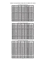
MITER CUT (MC)
The miter cut is intended for use as a termination for a horizontal
discharge. It is designed to minimize the entry of rainwater
when installed in the proper orientation. Note that the miter cut
is a single wall part and requires a clearance of 18” (457) to
combustibles.
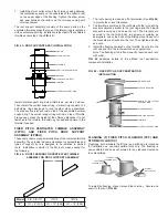
The miter cut is equiped with a birdscreen at the short side of
the miter (See
FIG. 51
). The miter must be installed so that the
long side of miter is on the top of the pipe to afford protection
from rain.
APPLIANCE CONNECTORS
SINGLE WALL BOILER ADAPTER (SBA)
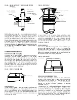
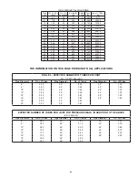
The single wall boiler adapter is the most commonly used
appliance connector. It is designed to clamp over a shank type
flue gas outlet. A thin layer of sealant, about 1” (25) wide is spread
on the end of the appliance outlet shank. Then the single wall
boiler adapter is placed around the shank covering the sealant.
The draw screw on the split tube is tightened to hold the single
wall boiler adapter in place (See
FIG. 52
).
The single wall boiler adapter is 6” (152) long. A 4” (102) long
variation is available on request.
FIG. 52 – SINGLE WALL BOILER ADAPTER
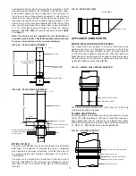
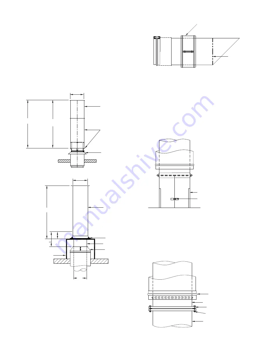
FIG. 53 – FLANGE ADAPTER
FIG. 51 - MITER CUT (MC)
CLOSURE BAND
BIRD SCREEN
CLAMPING SCREW
BOILER OUTLET SHANK
CASING CLOSURE INCLUDED
FLANGE ADAPTER
FLANGE GASKET (BY OTHERS)
BOLT AND NUT (BY OTHERS)
APPLIANCE OUTLET
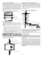
FIG. 50B – STACK HEAD ASSEMBLY
FLANGE ADAPTER (FA)
The flange adapter is intended for use as a connection to a Class
125 or 150 ANSI pipe flange. This type of connection requires a
flange gasket and bolt set supplied by the installer. The gasket
and bolts are typically sold by pipe, valve and fittings houses as
an “NBG” set.
FIG. 53
illustrates a typical installation.
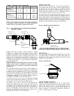
For diameters 26” thru 48” the chimney flue is terminated 9” (229)
below the required height for the installation (consult local codes).
A stack head adapter section is attached to the top section of
the chimney using a flange band and sealant. A closure ring is
attached to the flue to protect the annular space between the
inner and outer walls from rain. A plate support is located 6” (152)
below the top of the stack head adapter and PSW (Single Wall)
pipe, one size larger then the nominal chimney size, is attached
to it. The PSW pipe is equal in height to 4 times the chimney
diameter (See
FIG. 50B
). For guying requirements see
TABLE
7 on Page 5
.
Note: The structural steel supports for the stackhead are
provided by the installer. The stackhead assembly is intended
for use as a termination only for vertical discharge.
FIG. 50A – STACK HEAD ASSEMBLY
19
60” (1524) MAX FREE
STANDING HEIGHT
I.D. X 4
PSW PIPE
INTEGRAL STACK
HEAD ADAPTER
CLOSURE RING
I.D. + 2” (51)
I.D.
PLATE SUPPORT
PSW PIPE
STACK HEAD ADAPTER
CLOSURE RING
ROOF
SUPPORT STRUCTURE
TO ROOF- SUPPLIED
BY INSTALLER
6” (152)
I.D. X 4
9” (229)
I.D. + 2” (51)


