ENGINE EXHAUST SYSTEM PRECAUTIONS
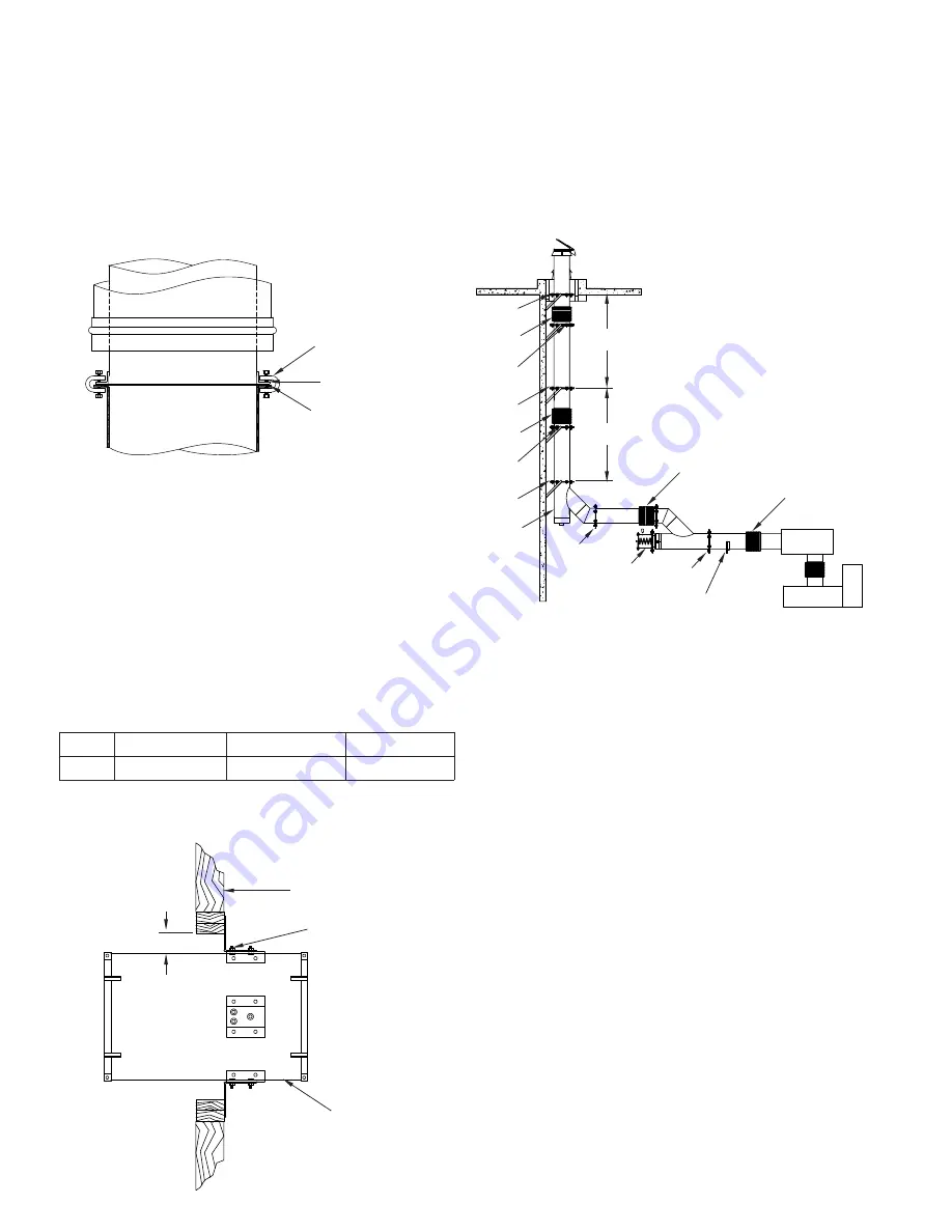
Engine exhaust systems require extra attention to support and
protection detail due to the possibility of delayed fuel ignition in
the exhaust system. It is important that all turns are protected
as illustrated in
FIG. 14, 16 & 18
or rigidly attached to structural
framing or walls.
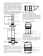
FIG. 56
illustrates some of the special
considerations that must be considered when designing an
engine exhaust system.
IMPORTANT: When installed vertically, bellows joint must
not support weight of stack. Locate bellows joint near the
lower side of fixed support as shown in FIG. 55.
The following components are primarily for use on engine or
turbine exhaust systems.
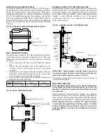
FIG. 55 - WALL PENETRATOR (WP)
4” MIN. (102)
COMBUSTIBLE WALLS
ATTACHED WITH 8D NAILS
OR #10 - 2” WOOD SCREWS
(4 PLACES)
WALL PENETRATOR
FIG. 56 – ENGINE EXHAUST CONSIDERATIONS
PLATE
SUPPORT
BELLOWS
JOINT
PLATE
SUPPORT
BELLOWS
JOINT
WALL
GUIDE
WALL
GUIDE
PLATE
SUPPORT
FIXED
TEE
PLATE
SUPPORT
PLATE
SUPPORT
BELLOWS JOINT
HALF
ANGLE
BELLOWS JOINT
MUFFLER
ENGINE
RELIEF
VALVE
3” (76) MAX.
EXPANSION
3” (76) MAX.
EXPANSION
20
BELLOWS JOINT (BJ)
Note: Standard bellows joints require greater clearance to
combustibles that double wall components. See Table 9 for
standard single wall and optional double wall bellows joints
for clearances.
Bellows joints are recommended for vibration and expansion
movement. This type of movement is typically encountered in
diesel engine or turbine exhaust applications.
FIG. 56
illustrates
typical bellows joint locations in a diesel engine exhaust system.
NOTE: Bellows Joints are required for expansion joints
in high pressure applications including engine or turbine
exhaust. Systems that use Bellows Joints are to use seal
clips (See TABLE 4 on Page 5) and additional joint sealant
per Page 23.
WALL PENETRATOR (WP)
This part is used to allow PIC/IPIC pipe to pass through non-fire
rated walls at reduced clearance. It consists of a 30” (762) long
thimble with mounting brackets. The wall penetrator is mounted
as follows:
1. Cut the opening in the wall. See chart below for opening
size.
2. Position the wall penetrator tube in the opening so it is
centered. Secure it to the wall with bolts or lag screws
(supplied.)
3. Install pipe so that it passes through the center of the wall
penetrator. Install lateral braces around the pipe casing.
Leave rings loose enough to slide along pipe.
4. Push the lateral rings into the wall penetrator centering the
tabs within the ends of the tube.
Model
PIC & IPIC-1
IPIC-2
IPIC-4
“X”
I.D. + 8” (203)
I.D. + 10” (254)
I.D. + 14” (356)
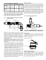
BOILER FLANGE ADAPTER (BFA)
The boiler flange adapter is used to connect PIC/IPIC pipe to
flanged appliance outlets other than those with ANSI pipe flanges.
Typical use includes boilers, water heaters and connection to
existing fabricated pipe. The adapter is designed to sandwich
the 1/2” inner pipe flange between the appliance outlet and the
boiler flange adapter (See
FIG. 54
). The boiler flange adapter is
shipped with beam clips used to clamp the BFA to the appliance
flange. The connection may also be drilled and bolted or welded
if desired.
FIG. 54 - BOILER FLANGE ADAPTER INSTALLATION
CLAMP
HALF RING
BOILER OUTLET FLANGE


