USE AND INSTALLATION OF INDIVIDUAL PARTS:
These instructions comprise both general and specific
requirements for all parts in the product line. Before specifying a
design or beginning an installation, these instructions should be
carefully reviewed.
PIPE WEIGHT
The average weight of the chimney, per foot of length, can be
calculated using the following formula:
PIC:
0.80 x diameter = lbs per foot
IPIC-1: 0.95 x diameter = lbs per foot
IPIC-2: 1.05 x diameter = lbs per foot
IPIC-4: 1.45 x diameter = lbs per foot
Example: 8IPIC-2: 1.05 x 8 = 8.4 lbs per foot
Chimney design should make provisions for support adequate to
ensure that chimney parts are not overloaded.
PART NUMBERS
These instructions identify Model PIC/IPIC parts by name of part
number in the text and illustrations. Actual parts also carry a flue
diameter prefix and a three digit “CTO” suffix which defines the
materials of construction, such as 24IPIC30-461 for a 24-inch
diameter double wall pipe section 30 inches long with Type 304
stainless steel inner wall, Type 316 stainless steel outerwall and a
1” insulation. (See Table 2 for further explanations of CTO codes).
TABLE 2
1st DIGIT
(INNER WALL)
2nd DIGIT
(OUTER WALL)
3rd DIGIT
(INSULATION)
4 = 304 S/S
6 = 316 S/S
A = ALUMINIZED STEEL
4 = 304 S/S
6 = 316 S/S
0 = 1” AIR SPACE
1 = 1” INSULATION
2 = 2” INSULATION
4 = 4” INSULATION
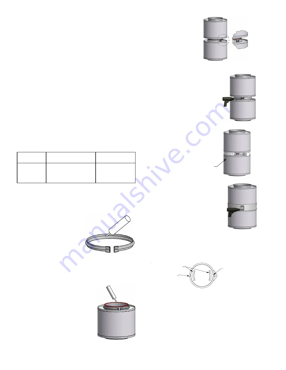
STEP 3
Join the two flanged ends of
the pipe sections.
STEP 4
Install the flange band around the flanges.
NOTE:
D o n o t l o c a t e V- C l a m p
hardware at the bottom side
of horizontal duct joints.
When installing flange band, tap lightly with
hammer around periphery of band while
tightening draw screws. This helps to align
flanges for the best seal. Do not overtighten
draw screws.
NOTE:
Allow sealant to cure 24 hours
before operating appliances.
STEP 5
(IPIC Installations Only)
Pack the void between inner and outer
walls with insulation strips.
STEP 6
Secure the outer casing with the closure
band.
When system is installed outdoors, the
upper side (upper half in the horizontal
position) of the closure band bead
should be sealed with P077 sealant to make
the casing watertight.
JOINT ASSEMBLY
The Model PIC/IPIC joint sealing system is designed for quick and
easy installation. For most applications follow Steps 1 through 6.
(For High Pressure applications, see additional steps.)
STEP 1
Fill the channel of the flange band with
the proper sealant and install below flange
of first pipe section
.
NOTE:
Sealant is to be supplied
by Metal-Fab. See
TABLE 3
on Page 23
for number of
tubes per joint.
CAUTION: THE USE OF ANY OTHER SEALANT ON THE
FLANGE SURFACE WILL NEGATE ALL LISTINGS OF THE
PRODUCT AND IMPAIR THE SEALING EFFECTIVENESS.
STEP 2
Apply a continuous bead of proper sealant
to one of the flanges to be joined
.
NOTE:
For gas temperatures up to 600ºF,
use P077 sealant.
For gas temperatures over 600ºF,
use P071 sealant.
For high pressure applications,
including ALL engine or
turbine exhaust applications, use P071 sealant.
INSULATION STRIPS (PROVIDED)
4
For all ENGINE EXHAUST and other HIGH PRESSURE
applications, perform Steps 1 through 3 above, then:
4. Install the seal clip(s) on the flanges 6”, 8” and 10” only.
(See
TABLE 4
).
Note: 6” & 8” require two seal clips located as shown.
5. Install the flange band around the flanges making sure
the joint is located so the seal clip overlaps both edges
of the joint.
6. Fill the space behind the flange band on both sides of
the flange with P071 pressure sealant (See
FIG. 3
).
7. Pack void between inner and outer walls with insulation
strips for IPIC installations.
8. Secure the outer casing with the closure band. Apply
sealant to closure band for exterior applications only.
See
JOINT ASSEMBLY
and
FIG. 3
for llustrations of the
joining process and finished joint.
SEAL CLIPS
SEAL CLIP BETWEEN
FLANGE AND FLANGE
BAND NOTCH
SEAL CLIP BETWEEN
FLANGE AND
FLANGE BAND BOLT
CONNECTION


