45º MANIFOLD TEE (45MT), DOUBLE LATERAL (DL)
For systems where minimizing flow resistance is desirable
or critical, a manifold tee having a 45º entrance to the trunk
is available. When used to make 90º turns, an additional 45º
elbow is required. It is particularly important to isolate the 45º
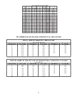
manifold tee from the effects of thermal expansion. This isolation
is typically accomplished by the use of a 2-axis support (See
FIG. 14
). Otherwise, the installation details and precautions are
similar to those for the 90º manifold tee.
MULTIPLE APPLIANCE BREECHINGS (HEADERS)
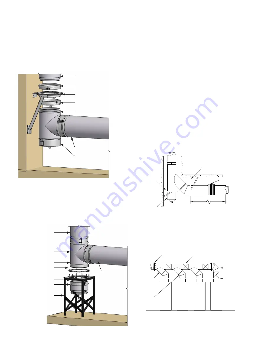
When 90º or 45º manifold tees are used to manifold multiple
appliances together, it is important to make provisions for
expansion of the manifold. An expansion joint should be installed
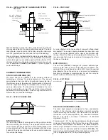
between tees (See
FIG. 15
). The manifold must be supported
properly by means of plate supports or wall support assemblies
arranged to protect the tees from bending forces.
30º, 45º OR 90º FIXED ELBOWS (30L) - (45L) - (90L)
Elbows are not designed to resist bending loads and must be
protected by structural reinforcement.
FIG. 16
depicts some
alternative methods for protection of elbows. Elbows may be
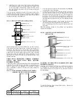
FIG. 14 - TWO-AXIS SUPPORT METHOD
MORE THAN 1/4” THERMAL
EXPANSION EXPECTED
BELLOWS JOINT OR
EXPANSION JOINT
PLATE SUPPORT ATTACHED
TO BUILDING STRUCTURE
DRAIN BUCKET
WALL SUPPORT
ASSEMBLY
FIG. 15 – LATERAL TEE MANIFOLD
PLATE SUPPORT
ADJUSTABLE LENGTHS
OR BELLOWS JOINT
PLATE SUPPORT
90° ELBOW
OUTLET
45° MANIFOLD
TEE
45° FIXED
ELBOW
8
STANDARD 90º TEE (90MT)
The 90º Manifold Tee (90MT) may be used to connect horizontal
to vertical when a cleanout access or drain is desired. If more
than 1/4” (6) of thermal expansion is expected between the
tee and the next fixed support point (the appliance outlet, for
example), the tee should be protected from bending moments
by use of an expansion joint or bellows joint. See the sections on
those fittings for additional information about compensation for
thermal expansion.
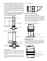
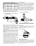
FIG. 12 – SUSPENDED TEE
PIPE RISER
HALF CLOSURE BAND
WALL SUPPORT ASSEMBLY
HALF CLOSURE BAND
TEE AT BASE OF RISER
DRAIN TEE CAP
PIPE SECTION
When a tee is used at the base of a riser, the preferred location
for support is above the tee, thus suspending the tee (
FIG. 12
). If
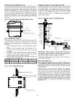
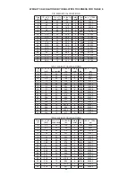
it is not possible to suspend the tee, it may be supported from the
base of the tee (
FIG. 13
). When this type of support is necessary,
access to the drain cap may be hindered. A drain bucket should
be used under the tee to allow access to the tee cap.
FIG. 13 – BASE SUPPORTED TEE
PIPE RISER
TEE
HALF CLOSURE BAND
CLAMP RING
(SEE NOTE BELOW)
HALF CLOSURE BAND
DRAIN BUCKET
STRUCTURAL STEEL
STAND (BY OTHERS)
PIPE SECTION
DRAIN TEE CAP (TC), CLEANOUT CAP
The unused port of a tee must be closed to prevent leakage of
flue gases. A drain tee cap is used to close the tee and drain
condensation or rainwater when the tee is installed at the base of
a rise. When the tee is to be used for cleanout or access purpose
only, a cleanout cap (TCN) is recommended. Both the drain tee
cap and the cleanout cap are equipped with closures, which
serve the dual purpose of maintaining the double wall clearance
to combustible and giving the cap a finished appearance.
The drain tee cap’s drain nipple must be connected to a suitable
disposal point. Any rain entering the chimney will wash down
and remove any combustion residue from the chimney flue. The
resulting effluent may be corrosive. The tee cap must be sealed
at the connection to the tee using the appropriate sealant for the
application. This will assure that moisture will drain through the
drain nipple, as intended.


