background image

23 


11


 Technical data 

Voltage 

230V~; 50Hz; 

Current consumed by regulator 

I = 0,04 A 

Maximum rated current 

6 (6) A 

Regulator protection rating 

IP20 

Ambient temperature 

0...50 

Storage temperature 

0...65 

Relative humidity 

5 - 85% without 
steam condensation 

Measuring range of 
temperature sensors CT4 

0...100 

Measuring range of 
temperature sensors CT6-P 

-35...40 

Accuracy of temperature 
measurements with sensors 
CT4 and CT6-P 

Terminals 

network  

screw terminals, wire 
cross-section area 
0.75 mm

2

 through 

1.5mm

2

, screwing 

torque 0.4Nm, 
insulation removed: 
6mm 
 

communication  

screw terminals, wire 
cross-section area up 
to 0.75mm

2

 , 

screwing torque 0.3 
Nm, insulation 
removed: 6 mm 
 

Display (TOUCH) 

Color display 
480x272 with touch 
panel 

External dimensions 

210x115x60 mm 

Total weight 

2 kg 

Standards 

PN-EN 60730-2-9 
PN-EN 60730-1


Software class 

Protection class 

Suitable to build into 
Class I devices 

Pollution degree 

2nd degree according 
to PN-EN 60730-1 

12


 Conditions of storage and 
transport 

The  regulator  cannot  be  exposed  to  direct 
effects  of  weather,  i.e.  rain  and  sunlight. 
Storage  and  transport  temperature  cannot 
exceed the range of -15…65 °C. 
During  transport,  the  device  cannot  be 
exposed  to  vibrations  greater  than  those 
typical of normal road transport. 
 

13


 REGULATOR INSTALLATION 

13.1


Environmental conditions 

Due to the risk of fire is prohibited to use the 
controller  in  explosive  gas  and  dust 
enviroment  (eg  coal).  Regulator  should  be 
separated using appropriate enclosure. 
In addition, controller cannot be used in the 
presence of water vapor condensation and be 
exposed to water. 

13.2


Installation requirements 

The  regulator  should  be  installed  by  a 
qualified and authorised fitter, in accordance 
with the applicable norms and regulations. 
The  manufacturer  bears  no  responsibility  for 
damages  caused  by  failure  to  observe  this 
manual.  The  regulator  is  to  be  built-in.  The 
regulator  cannot  be  used  as  a  stand-alone 
device.  The temperature  of the ambient and 
the  fitting  surface  cannot  exceed  the  range 
of  0  -  50˚C.  The  device  consists  of  two 
modules: control panel and working module. 
Both  elements  are  connected  with  electric 
wire.  

13.3


Assembly of TOUCH control panel 


The Control Panel is intended to be installed 
in  a  mounting  plate.  Make  sure  there  is 
sufficient thermal insulation between the hot 
walls of the boiler and the control panel and 
wiring.  The  amount  of  space  needed  to 
properly install the control panel is illustrated 
below.  Follow  the  guidelines  below  when 
installing the Panel. 


Make  an  opening  in  the  mounting  plate 
according to the following illustration. 

Summary of Contents for ecoMAX860P2-T

Page 1: ...C SOLID FUEL FIRED BOILERS WITH INGITION GUTTER AND RETORT FEEDERS INSTALLATION AND OPERATING MANUAL ISSUE 1 0 APPLIES TO SOFTWARE MODULE A B PANEL v06 XX XX v06 XX XX 11 2015 functions available in t...

Page 2: ...2...

Page 3: ...VERHEATING STB LIMITER OPEN 18 9 10 MAX EXHAUST TEMPERATURE EXCEEDED SENSOR DAMAGE DANGER 18 9 11 LACK OF COMMUNICATION 18 9 12 UNSUCCESSFUL ATTEMPT OF BUFFER LOADING 18 9 13 FAN OR FAN SPEED SENSOR F...

Page 4: ...flame going back to the fuel feeder etc The regulator is intended for boiler manufacturers Before applying the regulator a boiler manufacturer should check if the regulator s mating with the given boi...

Page 5: ...to two parts for user and fitter Yet both parts contain important information significant for safety issues hence the user should read both parts of the manual We are not responsible for any damages c...

Page 6: ......

Page 7: ...REGULATOR INSTRUCTION MANUAL ecoMAX860P2 T...

Page 8: ...Night time decrease boiler On No Yes Reduction value Schedule HUW settings HUW preset temperature HUW pump mode Off Priority No priority HUW container hysteresis HUW disinfection Night time decrease...

Page 9: ...been reached of preset boiler temperature for active time intervals increase of preset boiler temperature for the time of HUW container filling increase of preset boiler temperature by mixer circuit i...

Page 10: ...lted Boiler operation cannot be continued automatically service crew must intervene After removing causes of impossibility to fire up the boiler must be restarted 8 5 OPERATION The fan operates contin...

Page 11: ...ime expires the regulator switches to EXTINGUISHING mode unless the boiler temperature decreases and the boiler automatically switches to OPERATION mode For the setting Supervision time 0 the regulato...

Page 12: ...ght time decrease and Service Settings CH and HUW settings The time settings of the circulation pump are analogous to the settings of night time decrease The pump will be off in the defined time perio...

Page 13: ...e heating cycle temperature by a constant value when the preset room temperature is reached Analogously as specified in the previous point not recommended or automatically continuously correct the hea...

Page 14: ...have good thermal insulation the heating curve can have lower value The regulator can increase or decrease the preset temperature calculated in accordance with the heating curve if it exceeds the tem...

Page 15: ...selected and confirmed YES fuel level is set to 100 Note Fuel may be replenished at any time without a need to wait for complete empty fuel tank Replenish fuel always to the level corresponding to 100...

Page 16: ...tom of the screen there is a button Upon activation of this key a quick selection menu appears To add new item to this menu hold respective icon pressed in pie menu for a while To remove selected item...

Page 17: ...er control is taken over by the emergency system and the boiler continues to operate Note operating in emergency mode is allowed only under user supervision and until the arrival of the service team t...

Page 18: ...igital communication link In case a cable of this link will be damaged an alarm will occur on the screen with the information Attention No communication The controller doesn t stop to operate and work...

Page 19: ...19 CONTROLLER INSTALLATION AND SERVICE SETTINGS MANUAL ecoMAX860P2 T...

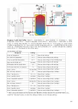
Page 20: ...rature set a high set temperature of the boiler In order to improve the water circulation in natural systems highlighted circuit in the figure use large nominal diameter pipes and four way valve avoid...

Page 21: ...ctivation temperature 55 C Menu service settings CH and HUW settings CH pump boiler pump YES Menu service settings CH and HUW settings Mixer 1 control CH activated Menu service settings Mixer 1 contro...

Page 22: ...ice settings buffer settings Buffer load activation temperature 50 Menu service settings buffer settings Buffer load deactivation temperature 75 Menu service settings buffer settings Mixer 1 control C...

Page 23: ...vibrations greater than those typical of normal road transport 13 REGULATOR INSTALLATION 13 1 Environmental conditions Due to the risk of fire is prohibited to use the controller in explosive gas and...

Page 24: ...In such case the user has access to the face plate of the executive module The cover may be composed from boiler elements surrounding the whole module The module cover does not provide resistance to...

Page 25: ...in accordance with this drawing the device has protection rate IP 20 from the front side of the executive module enclosure specified on the rating plate From the side of the terminals the casing has p...

Page 26: ...ation with low voltage devices below 12 V Connecting mains supply 230V to terminals 22 49 and to transmission connectors RS485 will damage the regulator and creates risk of an electric shock Tips of t...

Page 27: ...1 temperature sensor M2 CT4 regulated circuit mixer 2 temperature sensor WS CT6 P weather sensor FT CT2S exhaust temperature sensor BP control panel B additional heating circuits control module lambd...

Page 28: ...RM4 mixer 4 room thermostat FS fuel level sensor used with the BU feeder H2 voltage output for controlling the auxiliary boiler or alarm signalling or hot usable water circulation pump RELAY relay L N...

Page 29: ...t to the temperature not exceeding 100 C 13 9 Connecting weather sensor The regulator cooperates only with a weather sensor of the CT6 P type The sensor should be installed on the coldest wall of the...

Page 30: ...s Boiler Settings Pump off by therm 13 13 Connection of reserve boiler The regulator can control a reserve boiler gas or oil fired eliminating the necessity of enabling or disabling this boiler manual...

Page 31: ...f boiler water is limited You are advised to get familiar with the position of the valve corresponding to its maximum opening before commencement of work so that you may ensure heat collection from th...

Page 32: ...ck whether the valve is properly connected 13 16 Connecting temperature limiter STB In order to prevent the boiler from overheating due to the regulator malfunction an STB safety temperature limiter o...

Page 33: ...ion method exhaust only water and exhaust Exhaust temperature fan reduction Return protection 4 way return protection Return hysteresis Min return temperature Valve closing Min boiler temperature Max...

Page 34: ...dditional module is connected or the parameter is hidden Manufacturer menu Reset counters Reset alarms Exhaust alarm temperature Flame return feed time Flame return detection delay Flame return alarm...

Page 35: ...n OPERATION mode cycle time Complete cycle time of fuel feeding in OPERATION mode OPERATION cycle time OPERATION feed time feeder standstill time Feeder efficiency Efficiency of the fuel feeder in kg...

Page 36: ...mum feeder temperature is displayed When this temperature is exceeded the feeder is engaged for a predefined time with a several minute pause If the temperature drops the regulator resumes normal oper...

Page 37: ...es on the hot usable water pump and opens the mixer circuits in order to cool the boiler down The regulator will turn the hot usable water pump when the temperature of this water exceeds the maximum v...

Page 38: ...oiler is on a satisfactory level the regulator will not change it in order to load the HUW tank buffer or mixer circuit The increase of the set boiler temperature for the period of loading the HUW tan...

Page 39: ...uator Thermostat select Options to choose from Shut down it cuts the influence of room thermostat upon the boiler operation Universal it turns on the no nc room thermostat coupled to 42 43 contacts it...

Page 40: ...emperature in the mixer circuit sensor is equal to the set temperature In order to avoid frequent actuator movements which can wear it down unnecessarily the parameter should only be regulated when th...

Page 41: ...ecoTOUCH control panel from the regulator housing Insert memory card into indicated slot Memory card should contain new software stored in the pfc format two files one with software for control panel...

Page 42: ...should be connected also when in the boiler is not in use This function can be enabled also when the regulator is turned off via keyboard regulator in STAND BY 17 4 Bunker feeder After connecting an a...

Page 43: ......

Page 44: ......

Page 45: ......

Page 46: ......

Page 47: ......

Page 48: ...Jacek Kucharewicz ul Sikorskiego 66 16 100 Sok ka Poland tel 48 85 711 94 54 www metalfachtg com pl...

Reviews: