28
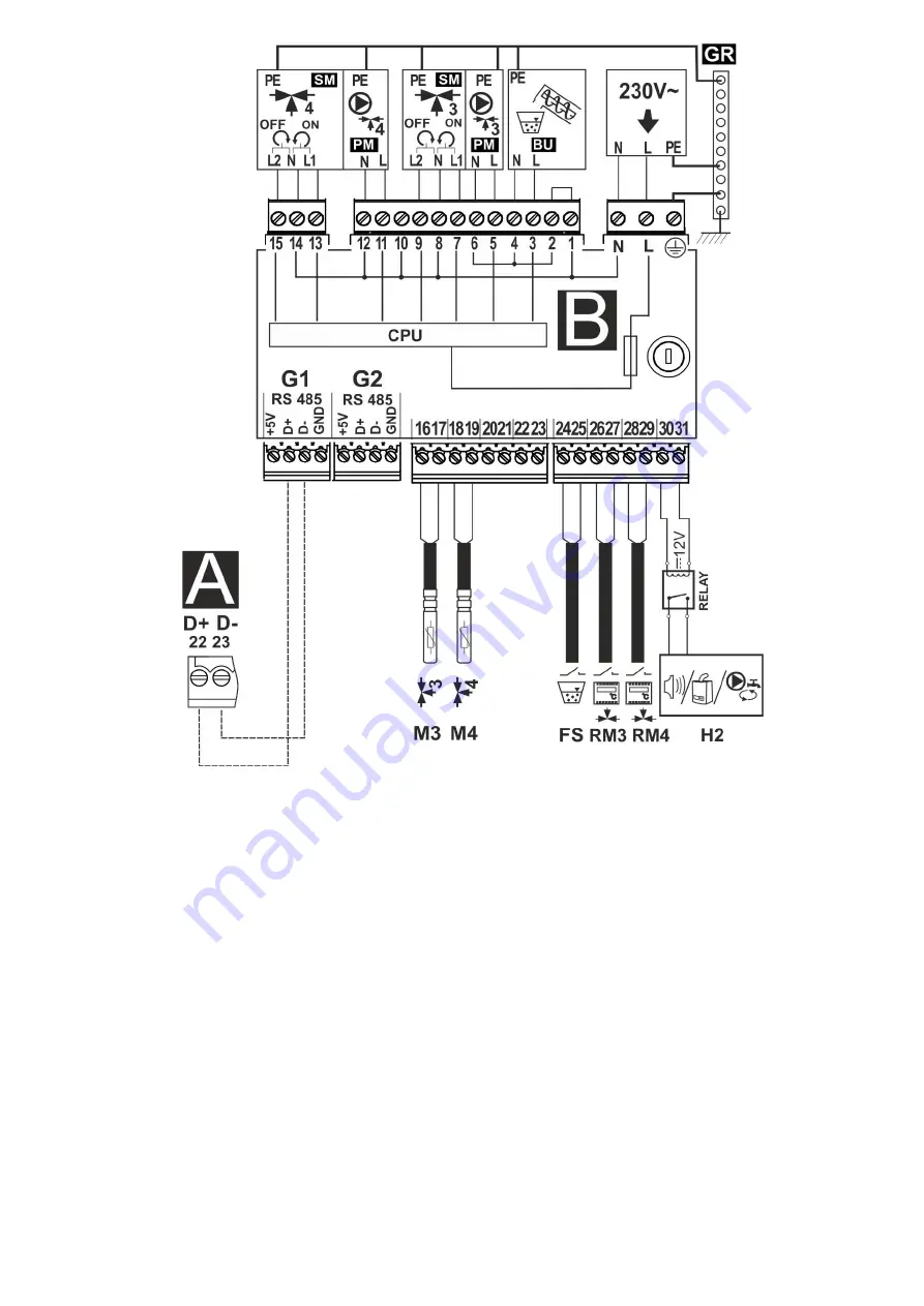
Wiring diagram - additional B module,
where: M3 - CT4 regulated circuit (mixer 3) temperature sensor,
M4 - CT4 regulated circuit (mixer 4) temperature sensor, RM3 - mixer 3 room thermostat, RM4 - mixer 4
room thermostat, FS - fuel level sensor used with the BU feeder, H2 - voltage output for controlling the
auxiliary boiler, or alarm signalling, or hot usable water circulation pump, RELAY - relay, L N PE - 230V~
power supply, PM3/4 - mixer 3/4 pump, SM3/4 - mixer 3/4 actuator, BU - fuel feeder from bunker to the
container by the boiler, CPU - controller, A - ecoMAX860P2-T Module A regulator.
Summary of Contents for ecoMAX860P2-T
Page 2: ...2...
Page 6: ......
Page 7: ...REGULATOR INSTRUCTION MANUAL ecoMAX860P2 T...
Page 19: ...19 CONTROLLER INSTALLATION AND SERVICE SETTINGS MANUAL ecoMAX860P2 T...
Page 43: ......
Page 44: ......
Page 45: ......
Page 46: ......
Page 47: ......

