14
INSTRUCTION MANUAL
–
T229, T241 FRONT LOADER
1.2 Front Loader Design
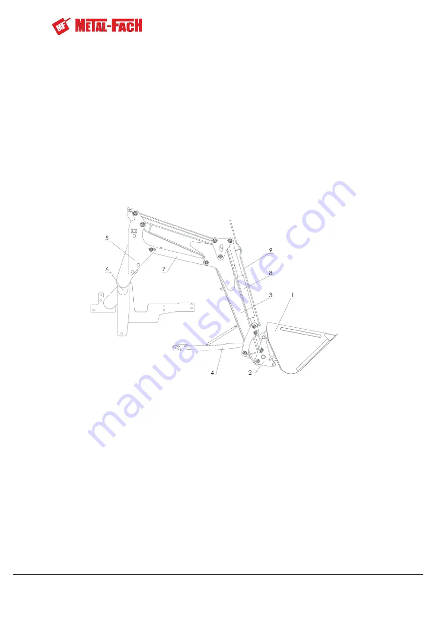
The Front Loader consists of the following assemblies:
−
1 - Work tool
−
2 - Coupling frame
−
3 - Boom
−
4 - Support
−
5 - Mounting plate
−
6 - Support frame
−
7 - Boom cylinder
−
8 - Frame cylinder
−
9 - Levelling indicator
−
10 - Valve block
Figure 3.
T229 Loader Design
The Front Loader is a hydraulic machine installed on the front of a farm tractor. The
Loader is supplied from
the tractor’s hydraulic system. Installation of the Loader is possible
owing to the support frame (6), which is permanently installed on the tractor.
FRAME INSTALLATION IS TO BE CARRIED OUT BY AUTHORISED SERVICE
CENTRES OF THE DEALER/MANUFACTURER.
Assemble the Loader by fastening the mounting plates (5), which are integral parts, to
the support frame (6) (Chapter 2.2.) The up-down motion of the boom (3) is achieved using the
boom cylinder (7)
–
a double-acting hydraulic cylinder. The rotary movement of the coupling
frame (2) is achieved by the frame cylinder (8)
–
a double-acting hydraulic cylinder. The Loader
can be supplied with a levelling indicator (optional) (9). The design of the Loader is
complemented by the support (4) used for attaching the Loader to a tractor and during storage
of the machine.
Summary of Contents for T229
Page 2: ......
Page 60: ...60 INSTRUCTION MANUAL T229 T241 FRONT LOADER NOTES...
Page 61: ...INSTRUCTION MANUAL T229 T241 FRONT LOADER 61...
Page 62: ...62 INSTRUCTION MANAL T229 T241 FRONT LOADER...
Page 63: ......


