32
INSTRUCTION MANUAL
–
T229, T241 FRONT LOADER
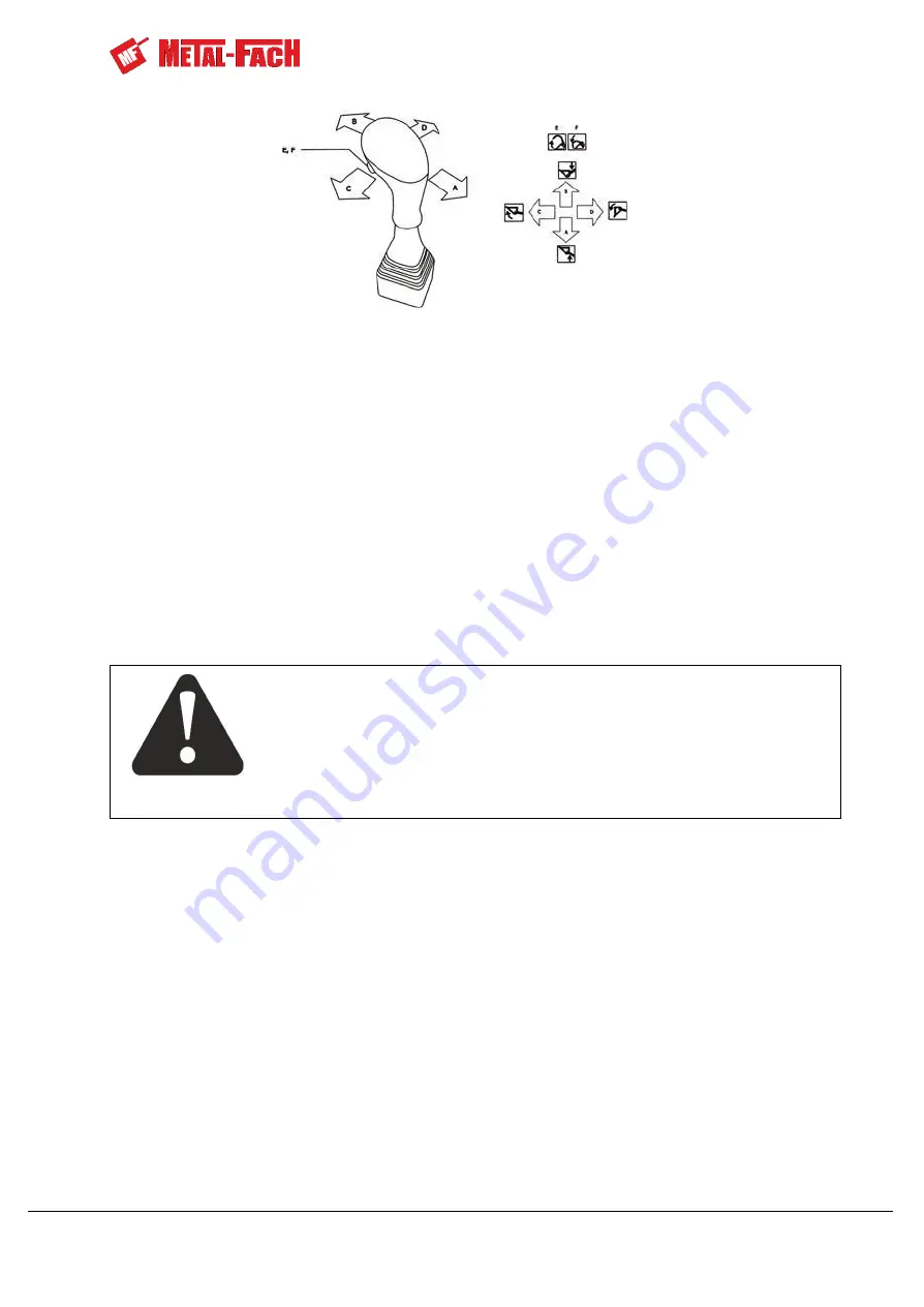
Figure 13.
Control functions of the Loader control lever
Figure 13 shows the control functions of the Loader joystick.
A - upward boom movement,
A - downward boom movement,
C - tool clockwise rotation,
D - tool anti-clockwise rotation,
E
–
opening the grabber,
F
–
closing the grabber.
3.2 Counterweight Control
The counterweight is controlled from the operator’s cab using internal levers designed
for controlling the lower three-point linkage connectors of the tractor.
3.3 Connecting the Loader Hydraulic System
Connect the loader valve block (4) to the hydraulic system of the tractor, as shown in
the diagram below.
Procedure:
−
disconnect the tractor valve block (7) from the pump (6),
−
use line (1) to connect the tractor pump to port P1 of the Loader valve block (6),
−
install a valve block connector (5) in port T1 of the Loader valve block (4),
−
using connector (5), connect the Loader valve block
(4) to port P1 of the tractor’s
hydraulic valve block (7) with line (2),
−
using the overflow line (3), connect the overflow port T2 of the Loader valve block (4)
with the tractor’s hydraulic oil tank.
Do not adjust the hydraulic distributor or the overflow valve. It has been
correctly set by the manufacturer.
WARNING
Summary of Contents for T229
Page 2: ......
Page 60: ...60 INSTRUCTION MANUAL T229 T241 FRONT LOADER NOTES...
Page 61: ...INSTRUCTION MANUAL T229 T241 FRONT LOADER 61...
Page 62: ...62 INSTRUCTION MANAL T229 T241 FRONT LOADER...
Page 63: ......


