background image

CorrTran MV Corrosion Monitor

15

3.3  Mounting safety procedures and hints 

The CorrTran MV must be installed in locations that are most susceptible to corrosion. 
In most cases, the highest levels of corrosion tend to occur where water is trapped or 
stagnant. 

The electrodes selected must reflect the same metal properties as the piping or other 
components susceptible to corrosion. For example, in applications where the pipe is made 
of stainless steel and the water pump’s impeller is made of carbon steel, the impeller will 
corrode faster than the pipe. In this case, it is advisable to select electrodes that are made 
of the same material as the pump’s impeller. 

3.3.1  Mounting requirements / scenarios 

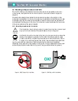
The transmitter should not be mounted in a pipe drop since the corrosive liquid 
may not be in full contact with the electrodes as shown in Figure 8. 

CorrTran MV should be mounted in the riser of a pipe near an elbow where the 
velocity is the highest. In general, CorrTran MV should be mounted in pipes 
or tanks at locations of highest liquid velocity and constant immersion, shown 
in Figure 9. For velocities greater than 20 fps, the protruding finger electrodes

must be protected. As noted above, high fluid velocities can also cause unwanted 
turbulence in the pipe due to the extension of the probe. Using an adjustable CorrTran MV 
probe with electrodes mounted flush to the wall of the pipe will eliminate this problem. 

Warning

Attention

OK!

Figure 8.  CMC Transmitter Installation

Figure 9.  CMC Transmitter Installation

Summary of Contents for CorrTran MV MS2900L

Page 1: ...tter Operator s Manual Metal Samples Company A Division of Alabama Specialty Products Inc 152 Metal Samples Rd Munford AL 36268 Phone 256 358 4202 Fax 256 358 4515 E mail msc alspi com Internet www me...

Page 2: ...cedures and hints 15 3 4 Installation instructions 19 4 WIRING 24 4 1 Quick wiring guide 24 4 2 HART introduction 25 4 3 Wiring with HART 25 4 4 Post installation check 26 5 CONFIGURATION AND COMMISSI...

Page 3: ...s used in a hazardous classified area must comply with all existing national standards CorrTran MV can be supplied with the certificates listed in Table 1 All technical personnel must be sufficiently...

Page 4: ...e safety precautions set forth herein Metal Samples does not certify test or inspect the installations of CorrTran MV for safety or other purposes Metal Samples disclaims liability for any personal in...

Page 5: ...Length 050 5 3 4 NPT 080 8 3 4 NPT 110 11 3 4 NPT 120 12 3 4 NPT or Flange 180 18 3 4 NPT or Flange 240 24 1 NPT 3 4 NPT or Flange 300 30 1 NPT 3 4 NPT or Flange 127 127 mm 3 4 NPT 204 204 mm 3 4 NPT...

Page 6: ...y are not installed the probe will not operate properly Please refer to Figure 17 on page 20 2 3 2 Transport Protect the transmitter electrodes from damage Do not attempt to carry the transmitter by i...

Page 7: ...on compression thread Adjustable epoxy glass probe and electrode 32 mm 1 25 20 mm 0 78 51 mm 2 00 29 mm 1 16 19 mm 0 75 60 mm 2 36 26 mm 1 02 NPT compression thread Adjustable stainless steel probe an...

Page 8: ...p Six pin circular connector 5 8 Packing gland assembly 3x electrodes ordered separately 3 4 1 6 1 FNPT Retractable probe electrode remote mount 5 9 I L Six pin connector cap Six pin circular connecto...

Page 9: ...PT 5 8 fitting 5 8 7 Insertion rod Blow out preventer optional 8 Retrievable probe adapter remote mount 3 88 5 1 4 Hollow plug assembly Heavy protective cover with 1 2 NPT HP flareweld access fitting...

Page 10: ...probe length 89 mm 3 5 EL EL 32 mm 1 25 for finger and 0 mm 0 for flush electrodes CMP adjustable probe The CMP adjustable probe Figure 2 is an adjustable probe commonly used in many field applicatio...

Page 11: ...s only available with both the remote and direct mounting options Electrodes shown in the picture are ordered separately Specifications Probe Body 1 4435 316L SS Hastelloy C Endcap Seal Glass Fill Mat...

Page 12: ...he remote and direct mounting options Electrodes shown in the picture are ordered separately Specifications Probe Body 1 4435 316L SS Hastelloy C Endcap Seal Glass Fill Material Epoxy Process Temperat...

Page 13: ...d a six pin connector welded in place A safety chain is also provided to prevent blowout The insertion length I L is calculated to the end of the electrode and can be specified by the customer This pr...

Page 14: ...y sealed three electrode end cap and a six pin connector welded in place A safety chain is also provided to prevent blowout The insertion length I L is calculated to the end of the electrode and can b...

Page 15: ...ated using one of the formulas bellow and must be specified by the customer This probe is only available with the remote mounting option Electrodes shown in the picture are ordered separately Specific...

Page 16: ...ler 3 3 1 Mounting requirements scenarios The transmitter should not be mounted in a pipe drop since the corrosive liquid may not be in full contact with the electrodes as shown in Figure 8 CorrTran M...

Page 17: ...int on the pipeline but should always be immersed in the corrosive material as shown in Figure 10 Figure 10 Correct CorrTran MV Pipeline Position A tee in the condensate return line Figure 11 is a goo...

Page 18: ...ormance As shown in Figure 12 This guarantees that the electrodes will always be immersed in the corrosive material Figure 12 CorrTran MV Located in Bypass Loop Installing separate CorrTran MV units w...

Page 19: ...he blow down of a Y strainer in Figure 15 and the discharge side of the basket strainer is shown in Figure 16 Figure 15 CorrTran MV Mounted in Y Strainer Figure 16 CorrTran MV Mounted in Basket Strain...

Page 20: ...ins the electronics and provides the 4 20 mA with HART output signal Probe There are two basic options direct mount and remote mount The remote mount probe is supplied with a 6 or 12 cable Electrodes...

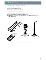
Page 21: ...probes 1 Insert the probe into the pipe 2 Adjust to desired depth 3 Apply 1 1 4 turns from hand tight to provide the seal as shown in Figure 18 Figure 18 CMP Adjustable and Fixed Probe Mounting For fi...

Page 22: ...op plate 4 must be assembled with label on top 5 Place lock washer 5 and nut 6 on to threaded rod 3 6 After sensor is mounted in to pipe slide safety bracket into place and tighten nut 6 to lock brack...

Page 23: ...0 in lb 33 9 N m 240 in lb Grafoil Packing 20 4 N m 240 in lb 20 4 N m 240 in lb 27 1 N m 240 in lb 27 1 N m 240 in lb Table 2 Recommended Torque Specifications Do not over tighten packing This will r...

Page 24: ...section 6 for ordering information CorrTran MV safety bracket assembly and installation See Figure 21 for detailed drawings 1 To assemble locking clamps 5 onto mounting bracket 2 angle clamp 5 out sl...

Page 25: ...data on the nameplate Switch off power supply before connecting the device Connect equipotential bonding to transmitter ground terminal before connecting the device Connect CorrTran MV as follows 1 Un...

Page 26: ...For this reason it is essential that isolators be installed between the transmitter and the control system if the I O card is not fully isolated from the ground An intrinsic safety isolator used in c...

Page 27: ...the following checks Is the probe secure and tightened to specified torque See section 3 4 3 Have the electrodes been cleaned See section 3 4 2 Is the terminal assignment correct See section 4 1 Is t...

Page 28: ...g their Device Description DD into the appropriate DTM for use with PACTware 5 2 Establishing communication with PACTware To establish communication between your CorrTran MV and other devices using PA...

Page 29: ...CorrTran MV connection To establish a connection with your CorrTran MV unit s Highlight the HART Communicator Right click and select Device Add device from the toolbar and add the CorrTran MV DTM You...

Page 30: ...sure what com port your modem is using go to your computer s device manager by opening the following windows Control panel System Hardware Device Manager Expand the Ports COM LPT to find out which co...

Page 31: ...CORRTRAN to the left of the screen Right click and select Connect from the toolbar Wait several seconds and the COM Parameter tab will display a symbol and a green check mark will appear in the bottom...

Page 32: ...ine parameters process variables The PACTware Process variables windows are read only and show the configurations associated with CorrTran MV s three process variables Each process variable has its ow...

Page 33: ...rocess Variables Primary Variable read only 5 3 3 Online variables diag service The Device Variables screen as shown in figure 34 provides an overview of all three process variables This screen is rea...

Page 34: ...cted by default To utilize this feature you must enable the password as seen in Figure 35 The default password is managers and can be changed after the password has been enabled After the password is...

Page 35: ...are set to zero Device Status indicates any parameters that are out of range or not working properly All the device status error codes are defined and expanded upon in Section 8 Troubleshooting Table...

Page 36: ...ws you to enter information about your CorrTran MV Some of the fields such as model and manufacturer are read only Figure 38 Basic Setup Device Information DV Assignment allows you to configure the Pr...

Page 37: ...e when general corrosion is assigned as the PV Figure 39 displays the Range and Units window When localized corrosion is assigned as the PV no units or range are selectable because localized corrosion...

Page 38: ...tup configuration window Figure 41 Detailed Setup Under the detailed setup menu you can update values in the following windows B User B User refers to the B value or Stern Geary voltage which is defau...

Page 39: ...e best accuracy LPR only A user defined Stern Geary voltage B User is specified and used for all LPR corrosion rate calculations Meas Mode Certain corrosion measurements can be turned off to give a fa...

Page 40: ...RTRAN to the left of the screen Right click and select Additional Functions Process Trend from the toolbar Your screen should appear as shown in Figure 42 Process Trend allows you to plot all three va...

Page 41: ...hole sampling cycle From the PACTware CorrTran MV REVIEW screen see page 40 collect the following data A Elect Area K Probe Const Calculated B Value From the PACTware CorrTran MV Online Parameters scr...

Page 42: ...hazardous substance purged therefrom and appropriate lockout tagout procedures observed in accordance with Section 1910 147 of the OSHA Regulations before CorrTran MV can be removed or the electrodes...

Page 43: ...m 3 4 NPT 305 305 mm 3 4 NPT or Flange 457 457 mm 3 4 NPT or Flange 610 610 mm 1 NPT 3 4 NPT or Flange 762 762 mm 1 NPT 3 4 NPT or Flange ADP Retrievable Probe Electrical Adaptor epoxy probe only Prob...

Page 44: ...lectrode Material Guide can be found in the Appendix Electrodes are sold in a pack of 3 6 1 4 Remote mount cable replacement C M C Electrode Material 0A see electrode material guide Note C M C R 0 2 C...

Page 45: ...f isolated barriers are offered Model Description KFD2 HLC Ex1 D IS HART loop converter with 3 distinct 4 20 mA outputs KCD2 STC Ex1 1 channel IS isolator KFD2 STC4 1 1 channel non IS signal condition...

Page 46: ...ting at 1 ANSI B 16 5 150 lbs available in 316L SS and Hastelloy C Retractable probe Adjustable 1 female NPT fitting and flanges starting at 1 ANSI B 16 5 150 lbs available in 316L SS and Hastelloy C...

Page 47: ...justable Measured in Siemens Output Output Signal 4 20 mA with HART protocol 2 wire Signal on Alarm Error information can be accessed via the following interfaces Current output 22 5 mA Digital interf...

Page 48: ...s Process Flow Rate Limits Finger electrodes Max 6 1 mps 20 fps Flush electrodes No limit on electrodes dependent on mechanical strength of probe body in the flow Mechanical Construction Design Dimens...

Page 49: ...X Cl I Div 1 2 Groups A D IEC Approval Patents U S patents 7 239 156 7 245 132 7 265 559 7 282 928 Ordering Information Ordering Information Metal Samples can provide detailed ordering information and...

Page 50: ...r the LRV or URV This can only happen if General Corrosion is assigned to the SV and the ranges are not set properly Extend the range values to include current data point See section 3 3 2 for more in...

Page 51: ...ypically this is an indication that there is too much build up on the surface of the electrodes and they need to be cleaned or that they have exceeded their useful life and should be replaced Corrosio...

Page 52: ...alculation resulting in a highly accurate self adjusting process specific corrosion rate calculation CorrTran MV can measure the general corrosion rate from 0 1000 mpy 0 25 mmpy Localized Corrosion Pi...

Page 53: ...e solution conductance in units of Siemens as the tertiary variable that is not scalable CorrTran MV requires a minimum solution conductance of 4 S in order to provide reliable corrosion data The solu...

Page 54: ...API 5L Grade B 11441 28 CME 0W API 52X 65 11440 94 CME 1C API 5L X52 STE 360 7 11443 31 CME 1F API 5L X60 11444 40 CME 1H API 5L Grd A 11443 89 CME 1L API 5L X42 11429 12 CME 1N Stainless Steel 304 1...

Page 55: ...NPT Remote Standard finger Kalrez L Fixed NPT flange Direct Flush N A M Fixed NPT flange Remote Flush N A N Adjustable NPT Direct Flush N A O Adjustable NPT Remote Flush N A P Retractable NPT Remote...

Page 56: ...CorrTran MV Corrosion Monitor 55 Default settings Figure 45 CorrTran MV default settings Figure 46 CorrTran pinout diagram...

Page 57: ...not supported by PACTware Please disregard those sections in the manual The programming tool for CorrTran EC is the Evaluation Tool package which you will find on the CD accompanying the unit 11 1 1...

Page 58: ...tial settings on the CorrTran EC and save them to the nonvolatile memory in the unit Timing Mode Sets the data logging interval of CorrTran EC GC Units General corrosion units Choices are mils year mp...

Page 59: ...n the accuracy of the calculation K Probe Constant You can update this value if you are using LPR Mode only If you are using Normal Mode the K constant will update automatically after the first measur...

Page 60: ...Tran for months under typical use and allow retrieval of data on several occasions Replacements are available However there may be a time when it is no longer possible to retrieve data from the unit D...

Reviews: