


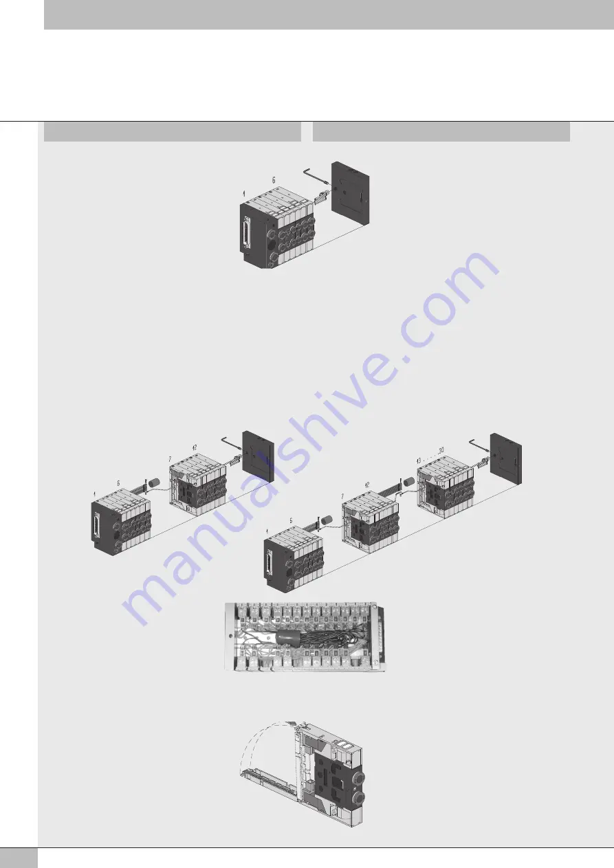
Per isole fino a 6 posizioni
Infilare i terminali ad occhiello dei cavi neri
e della prolunga per comune nella vite e
bloccare con il dado. Avvitare la bussola
isolante sulla vite, quindi posizionarla nella
apposita sede del terminale cieco di chiusura
e bloccarla con il grano M5, facendo
attenzione che nessun contatto tocchi la parte
metallica del terminale o della valvola.
For islands with up to 6 positions
Slide the lug terminals of the black cables and
the common extension terminal onto the screw
and lock down with the nut.
Tighten the insulating bush onto the screw
and then position it in the seat provided in the
blind closing terminal and block it with the
grub screw.
Ensure that no contacts touch the metal part of
the terminal or the valve.
Kit supporto connettore con cuffia di protezione
blu senza prolunga intermedia per comune
- Isole con oltre 6 posizioni -
Infilare i terminali ad occhiello dei cavi neri e
della prolunga per comune nella vite e bloccare
con il dado. Isolare i fili del comune inserendoli
nella cuffia di protezione e collocarli nella
posizione più idonea sfruttando lo spazio
disponibile.
For connector support kit with blue protection
hood and without intermediate common extension
- For islands with more than 6 positions -
Slide the lug terminals of the black cables and
the common extension terminal onto the screw
and lock down with the nut. Insulate the common
wires by inserting them into the protection hood
and connect them in the most suitable position,
exploiting the space available.
Terminare il montaggio incastrando lo sportello
posteriore nella piastrina superiore.
End the assembly by engaging the rear door
with the upper plate.
Kit supporto connettore con cuffia di protezione arancio e prolunga
intermedia per comune
- Per isole con oltre 6 posizioni -
Infilare i terminali ad occhiello dei cavi neri, della prolunga per comune
e della prolunga intermedia per comune nelle viti e bloccare con il dado.
Isolare i fili del comune inserendoli nella cuffia di protezione e collocarli
nella posizione più idonea sfruttando lo spazio disponibile.
Avvitare la bussola isolante sulla vite, quindi posizionarla nella apposita
sede del terminale cieco di chiusura e bloccarla con il grano M5,
facendo attenzione che nessun contatto tocchi la parte metallica del
terminale o della valvola.
For connector support kit with orange protection hood and with
intermediate common extension
- For islands with more then 6 positions -
Slide the lug terminals of the black cables, the common extension
terminal and lug terminal of the intermediate common extension onto the
screws and lock down with the nuts. Insulate the common wires by
inserting them into the protection hood and connect them in the most
suitable position, exploiting the space available.
Tighten the insulating bush onto the screw and then position it in the seat
provided in the blind closing terminal and block it with the grub screw.
Ensure that no contacts touch the metal part of the terminal or the valve.
4


