background image

6

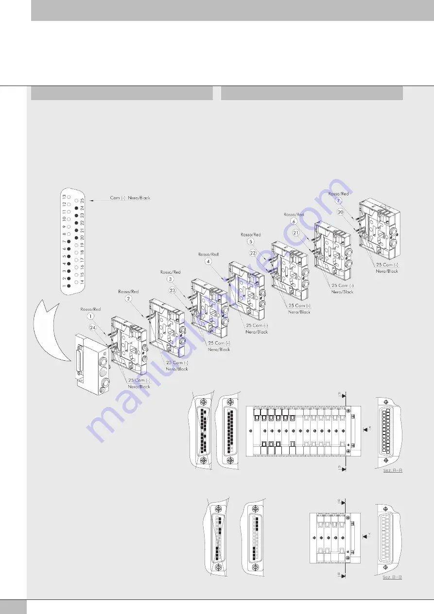
SCHEMA CABLAGGIO E COLLAUDO ELETTRICO DEL CONNETTORE 

D-SUB 25 POLI

Controllare che il connettore D-sub 25 poli presenti i contatti che 

fuoriescono a partire dalla sede n°1 e ad incrementare (1 - 2 - 3 - 4 ...) 

e dalla sede n°25 e a decrementare (25 - 24 - 23 - 22 ...) senza salti di 

sede (vedi viste X - Y). Controllare che il numero dei contatti maschio sia 

uguale al numero degli elettro 1. Connettere il polo negativo della 

tensione 24VDC al contatto 25 del connettore D-sub a 25 poli. Verificare 

che connettendo il polo positivo della tensione 24VDC al contatto 1 del 

connettore D-sub a 25 poli si illumini il led dell’elettropilota 1. Ripetere 

l’operazione per tutti gli elettropiloti connessi (max 24 elettropiloti).

Check that the 25 pole D-sub connector has contacts that protrude 

starting from position No. 1 - and increasing (1 - 2 - 3 - 4 ...) and from

position No. 25 and decreasing (25 - 24 - 23 - 22 ...) without missing 

any positions (see views X-Y). Check that the number of male contacts 

is equal to the number of electro- 1. Connect the negative pole 

of the 24VDC voltage to contact 9 of the 9 pole D-sub connector. Check 

that by connecting the positive pole of 24VDC voltage to contact 1 of the 

25 pole D-sub connector the LED of the electro-pilot 1 comes on. Repeat 

the operation for all the electro-pilots connected (max. 24 electro-pilots).

WIRING DIAGRAM AND ELECTRICAL TESTING FOR THE 25 POLE 

D-SUB CONNECTOR

12

10

12

10

11

45

29

3

8

1

67

14

11

45

29

3

8

1

67

14

13

15

16

17

18

19

20

21

22

23

24

25

13

15

16

17

18

19

20

21

22

23

24

25

12 11

7

8

9

10

19

18

17

16

21

20

23

22

1

2

24

3

4

5

6

25

14

24

31

3

1

24

23

22

.....

...

.

.

.

.

.

..

23

22

1

2

24

3

4

25

14

24

31

3

1

24

23

22

.....

...

.

.

.

.

.

..

Cablaggio errato

Incorrect wiring

Vista da Z

View from Z

13 posizioni

13 positions

Cablaggio errato

Incorrect wiring

Vista da Y

View from Y

4 posizioni

4 positions

12

10

12

10

11

45

29

3

8

1

67

14

11

45

29

3

8

1

67

14

13

15

16

17

18

19

20

21

22

23

24

25

13

15

16

17

18

19

20

21

22

23

24

25

12 11

7

8

9

10

19

18

17

16

21

20

23

22

1

2

24

3

4

5

6

25

14

24

31

3

1

24

23

22

.....

...

.

.

.

.

.

..

23

22

1

2

24

3

4

25

14

24

31

3

1

24

23

22

.....

...

.

.

.

.

.

..

Summary of Contents for Multimach

Page 1: ...I GB MANUALE D USO USER MANUAL MULTIMACH MULTIMACH ...

Page 2: ...a si incastrino nella successiva e anche nell apposita sede del terminale cieco Continue in the same way to assemble the other valves as far as the blind terminal Make sure that the small teeth A of each plate engage with the successive ones and also with the relevant seat in blind terminal Dopo il montaggio è necessario effettuare il collaudo pneumatico dell isola controllando le tenute generali ...

Page 3: ...venth up to the twelfth position use the 7 12 valve plug in connector kit code 0226180400 and then use the 13 30 valve plug in connector kit code 0226180401 for the thirteenth position onwards ELECTRIC WIRING Inserire il terminale del cavo prolunga per comune nella sede del connettore D sub contrassegnato dal numero 25 9 secondo il tipo di connettore Inserire i terminali dei cavi rossi degli elett...

Page 4: ...wires by inserting them into the protection hood and connect them in the most suitable position exploiting the space available Terminare il montaggio incastrando lo sportello posteriore nella piastrina superiore End the assembly by engaging the rear door with the upper plate Kit supporto connettore con cuffia di protezione arancio e prolunga intermedia per comune Per isole con oltre 6 posizioni In...

Page 5: ...i elettropiloti connessi max 8 elettropiloti Check that the 9 pole D sub connector has contacts that protrude starting from position No 1 and increasing 1 2 3 4 and from position No 9 and decreasing 9 8 without missing any positions see view Z Check that the number of male contacts is equal to the number of electro pilots 1 Connect the negative pole of the 24VDC voltage to contact 9 of the 9 pole ...

Page 6: ... number of male contacts is equal to the number of electro pilots 1 Connect the negative pole of the 24VDC voltage to contact 9 of the 9 pole D sub connector Check that by connecting the positive pole of 24VDC voltage to contact 1 of the 25 pole D sub connector the LED of the electro pilot 1 comes on Repeat the operation for all the electro pilots connected max 24 electro pilots WIRING DIAGRAM AND...

Page 7: ...nnector from the electro pilot Press the point indicated with the screw driver or your fingers and extract the connector in the direction indicated Montaggio delle staffe di collegamento su barra DIN Fissare le staffe sia sul terminale cieco B e sul terminale di ingresso A mediante la vite in dotazione Fig 1 Agganciare la parte posteriore della staffa alla barra DIN e premere nella direzione indic...

Page 8: ...ONE Per tubo Ø8 NON UTILIZZARE RACCORDI AUTOMATICI SERIE R UTILIZZARE SOLO RACCORDI AUTOMATICI MINIATURIZZATI SERIE RL FOX NOTE For tube Ø8 DO NOT USE R SERIES PUSH IN FITTINGS USE JUST RL FOX SERIES MINIATURE PUSH IN FITTINGS Ø8 RL9 Ø8 RL8 Ø8 RL7 Ø8 R9 Ø8 R8 Ø8 R7 Ø8 ...

Reviews: