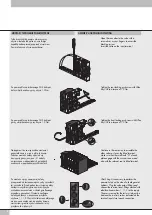
Dla wysp z 6 zaworami
Drugą końcówkę wspólnego czarnego
przewodu masowgo umocować na śrubie
i zabezpieczyć nakrętką. Następnie śrubę
zamontować w tulei izolacyjnej i umieścić
w odpowiednim gnieździe w pokrywie
tylnej. Tuleję zablokować wkrętem bez łba.
Należy upewnić się że przewód masowy nie
dotyka żadnych metalowych części wyspy
zaworowej.
For islands with up to 6 positions
Slide the lug terminals of the black cables and
the common extension terminal onto the screw
and lock down with the nut.
Tighten the insulating bush onto the screw
and then position it in the seat provided in the
blind closing terminal and block it with the
grub screw.
Ensure that no contacts touch the metal part of
the terminal or the valve.
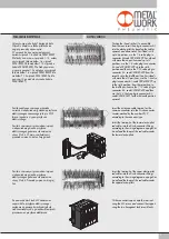
Zabezpieczenie przewodów za pomocą
niebieskiego kaptura ochronnego.
-
Dla wysp powyżej 6 zaworów.
-
Wszystkie czarne przewody zaworów należy
połączyć ze wspólnym przewodem masowym
bezpośrednio wpiętym w gniazdo 25/9 przy
użyciu śruby z nakrętką. Miejsce łączenia
przewodów dodatkowo należy zabezpieczyć
za pomocą niebieskiego kapturka ochronnego i
umieścić w wolnej przestrzeni między pilotami.
For connector support kit with blue protection
hood and without intermediate common extension
- For islands with more than 6 positions -
Slide the lug terminals of the black cables and
the common extension terminal onto the screw
and lock down with the nut. Insulate the common
wires by inserting them into the protection hood
and connect them in the most suitable position,
exploiting the space available.
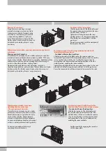
Po montażu przewodów elektrycznych
zamykamy drzwiczki obudowy.
End the assembly by engaging the rear door
with the upper plate.
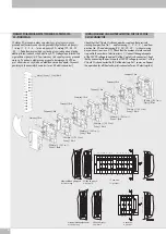
Zabezpieczenie przewodów za pomocą pomarańczowego kaptura
ochronnego.
Dla wysp powyżej 6 zaworów.
Wszystkie czarne przewody zaworów należy połączyć ze wspólnym
przewodem masowym bezpośrednio wpiętym w gniazdo 25/9 przy
użyciu śruby z nakrętką. Miejsce łączenia przewodów dodatkowo należy
zabezpieczyć za pomocą pomarańczowego kapturka ochronnego i
umieścić w dowolnej przestrzeni między pilotami.
Następnie śrubę zamontować w tulei izolacyjnej i umieścić w
odpowiednim gnieździe w pokrywie tylnej. Tuleję zablokować wkrętem
dociskowym bez łba. Należy upewnić się że przewód masowy nie
dotyka żadnych metalowych części wyspy zaworowej.
For connector support kit with orange protection hood and with
intermediate common extension
- For islands with more then 6 positions -
Slide the lug terminals of the black cables, the common extension
terminal and lug terminal of the intermediate common extension onto the
screws and lock down with the nuts. Insulate the common wires by
inserting them into the protection hood and connect them in the most
suitable position, exploiting the space available.
Tighten the insulating bush onto the screw and then position it in the seat
provided in the blind closing terminal and block it with the grub screw.
Ensure that no contacts touch the metal part of the terminal or the valve.
4


