background image

12

SSG 16 | Version 2.01

Spare parts drawing

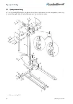
12  Spare parts drawing

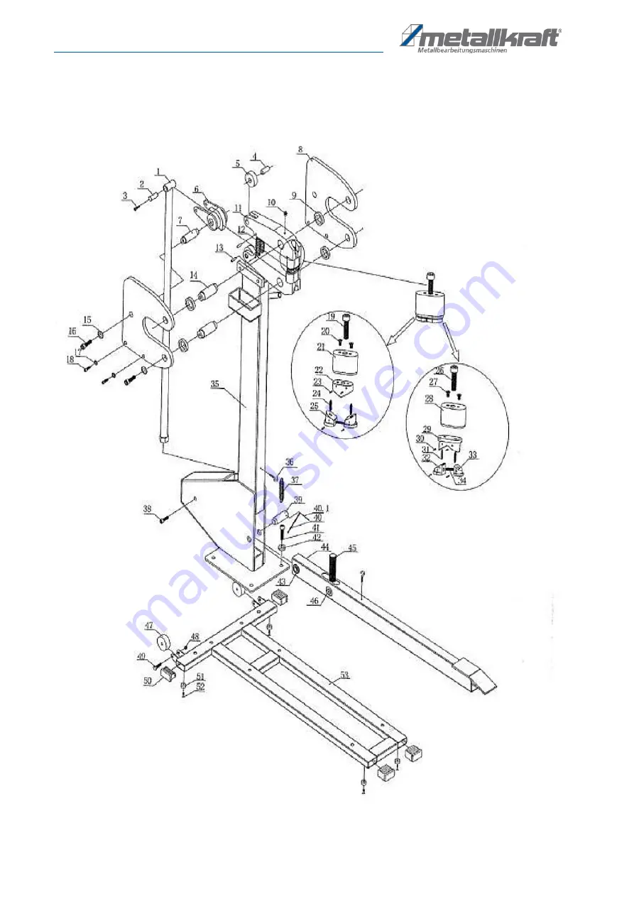
The following drawing are intended to identify the required spare parts in the event of service. If applicable, submit a copy 
of the parts drawing including the highlighted components to your authorized retailer.

Fig. 22: Spare parts drawing  SSG 16

Summary of Contents for 3776103

Page 1: ...SSG 16 Instruction Manual SSG 16 Compressing and stretching machine SSG 16 ...

Page 2: ...prohibited if not explic itly permitted Contraventions are liable to compensa tion Subject to technical modifications and error Contents 1 Introduction 3 1 1 Copyright 3 1 2 Costumer service 3 1 3 Limitation of liability 3 2 Safety 3 2 1 Symbol explanation 3 2 2 Obligations of the operating company 4 2 3 Requirements to staff 4 2 4 Personal protective equipment 5 3 Intended Use 5 3 1 Residual risk...

Page 3: ...luable experience and knowledge gained from using the application which then could be shared and be valuable to develop our products even further 1 3 Limitation of liability All information and notes in these operating instructions were summarised taking the applicable standards and rules the state of the art and our long term knowledge and experiences into consideration In the following cases the...

Page 4: ... Furthermore she must in struct the staff in regular intervals and inform them about the hazards The operator must provide the necessary protec tive equipment to the staff and order the use of the necessary protective equipment in a binding way Furthermore the operating company is responsible to keep the machine always in a technically flawless state Thus the following applies The operator must en...

Page 5: ...essing and stretching machine is used for universal use in the workshop and construction site area for upsetting and stretching sheet metal The version SSG 16 can handle a maximum plate thickness of 1 5 mm Proper use also includes compliance with all information in this manual Any use beyond the intended use or otherwise is considered misuse Unauthorized modifications or alterations to the device ...

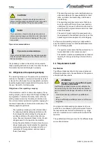
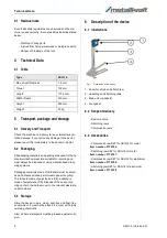
Page 6: ...per recycling The foils are made of polyethylene PE padding is made of polystyrene PS Dispose of these at a recy cling center or hand them over to the relevant waste dis posal company 5 3 Storage Store the device in a dry clean dust free and frost free environment It must not be placed in a room with highly oxidising chemicals Also all bare metal parts must be greased against corro sion 6 Descript...

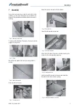
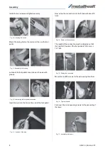
Page 7: ...3 Drilling Mount the foot pedal to the rear axle using the M10 screws Fig 4 Mount the foot pedal Put some fat on the axle Fig 5 Greasing the axle Mount the axle to the end of the foot pedal Fig 6 Mount the axle Insert the foot pedal into the rack Fig 7 Mount the foot pedal Move the foot pedal in the main unit while inserting the screw into the corresponding opening Fig 8 Inserting the screw Hold t...

Page 8: ...on Insert the axle into the hole at the end of the foot pedal Fig 13 Insertion of the axle Now screw the connection into the thread with about 15 turns Fig 14 Screw in the connection The length of the connection must be adjusted so that the height of the side of the foot pedal is 190 5 mm 12 7 mm Fig 15 Setting the connection Mount the two M8 screws for the axle and tighten them Fig 16 Tighten the...

Page 9: ... 1 Operation and adjustment Please make sure that the jaws are properly attached to the body of the device and the body part is fixedly moun ted on the associated stand The opening and closing of the tool teeth is only possible by pressing the foot pedal see exploded view Place the sheet to be processed in the middle of the jaws and press the foot pedal Note The work carried out should be within t...

Page 10: ... persons Insufficiently qualified persons can not assess the risks associated with repair work on the upsetting and stretching equipment and expose themselves and others to the risk of serious injury All maintenance work should only be carried out by qualified persons NOTE After care maintenance and repair work check that all panels and guards are correctly mounted on the upsetting and stretching ...

Page 11: ...g and stretching machine SSG 16 must be ordered The wheel has the number 47 in the spare parts drawing 1 By ordering spare parts send a copy of the spare parts drawing 1 with the marked part wheel and marked po siton number 47 to the dealer or spare parts depart ment and provide the following information Type of device Compressing and stretching ma chine SSG 16 Item number 3776103 Drawing number 1...

Page 12: ...rts drawing The following drawing are intended to identify the required spare parts in the event of service If applicable submit a copy of the parts drawing including the highlighted components to your authorized retailer Fig 22 Spare parts drawing SSG 16 ...
Page 13: ...Notes SSG 16 Version 2 01 13 13 Notes ...

Page 14: ...www metallkraft de ...

Reviews: