background image

14

RBM 1305-15 E | Version 1.02

Cleaning, maintenance and service/repair

.

Step 3: After the formed semicircle, reinsert the un-

shaped material into the roller and turn the actua-
tion handle clockwise to form a complete circle.

Withdrawal of the workpiece

Step 1: After completing the bending process, support 

the workpiece with a crane.

Step 2: Move the lower and rear roller down.

Step 3: Release the lock on the top roller.

Step 4: Swing top roller out.

Fig. 14: Swing out of the tp roller

Step 5: Remove workpiece. Use a crane to support the 

workpiece.

Step 6: Swing the top roller back into the bearing and 

lock it. 

Fig. 15: Workpiece withdrawal with lifting device

9

Cleaning, maintenance and service/
repair

NOTE!

It is important that the roller rotates while you oper-
ate the cam lever. When the cam lever is engaged 
while the rollers are not rotating, a noticeable flat 
spot or line is formed across the width of the mate-
rial.

ATTENTION!

When the upper roller is tilted, the upper roller must 
not be overloaded by the workpiece. The workpiece 
must be supported by a crane.

Tips and recommendations

To ensure that the bending machine is always in 
good operating condition, regular care and mainte-
nance work must be carried out.

DANGER!

Danger due to insufficient qualification of 
persons!

Insufficiently qualified personnel can not assess the 
risks involved in maintenance work on the machine 
and expose themselves and others to the risk of seri-
ous injury.
- All maintenance work should only be carried out by 

qualified persons.

DANGER!
Danger to life due to electrical shock! 

There is a danger to life when in contact with live 
components.
-  Always unplug the appliance before cleaning and 

maintenance.

-  Connections and repairs of the electrical equip-

ment may only be carried out by a qualified electri-
cian.

NOTE!

Before servicing and maintaining the bending 
machine, the maintenance instructions must be read 
carefully. Handling the Bending Machine is only per-
mitted to persons who are familiar with the Bending 
Machine.

ATTENTION!

After servicing, maintenance and repair work, check 
that all panels and guards are properly installed on 
the machine again and that there is no more tools 
inside or in the working area of the round bending 
machine.

Damaged safety devices and parts must be repaired 
or replaced by the customer service.

Summary of Contents for 3781305

Page 1: ...RBM 1305 15 E Operating Instructions RBM 1305 15 E Bending Machine RBM 1305 15 E...

Page 2: ...t 3 1 2 Customer service 3 1 3 Limitation of liability 3 2 Safety 3 2 1 Symbol explanation 3 2 2 Requirements to staff 4 2 3 Personal protective equipment 4 2 4 General safety regulations 5 2 5 Safety...

Page 3: ...s interested in valuable experience and knowledge gained from using the application which then could be shared and be valuable to develop our products even further 1 3 Limitation of liability All info...

Page 4: ...may only be performed by specialist per sonnel of the manufacturer Other personnel is not au thorized to perform these works Please contact our cus tomer service for the execution of all arising work...

Page 5: ...e round bending machine from moisture Make sure that no parts are damaged before using the Bending Machine Damaged parts must be replaced immediately to avoid danger sources Do not overload the bendin...

Page 6: ...pieces Danger from the ingress of clothing and objects During set up and set up work it may be necessary to dismantle on site protective equipment This creates various residual risks and potential dan...

Page 7: ...collection point for recyclable materials or to the waste disposal company which looks after your region 5 3 Storage Store the bending machine thoroughly cleaned in a dry clean and frost free environ...

Page 8: ...ottom roller Wire insert groove on the top and rear roller 6 2 Safety switch For the safety of the operating personnel the machine is equipped with a safety switch and EMERGENCY STOP brackets When the...

Page 9: ...ers and the motor corresponds to the indicated di rection of the arrow In some cases a reverse connection may cause the motor to burn out It must also be checked whether the direction of rotation of t...

Page 10: ...achine and expose themselves and others to the risk of serious or fatal injuries All work should only be carried out by qualified per sons Keep inadequately qualified persons out of the work area WARN...

Page 11: ...iece from the machine the right hand lock of the upper roller must be released and the upper roller must be removed from the guide Fig 6 Lock of the top roller 8 1 Work process Step 1 Before starting...

Page 12: ...rdboard for the desired radius Always work the workpiece in the center of the rollers Fig 8 Position the workpiece in the middle of the rollers Calculation of the workpiece length Fig 9 Calculation of...

Page 13: ...ng in the material being fed through the machine The hand wheel is equipped with a scale that helps the operator to adjust Bending process Step 1 After adjusting the diameter insert the material on th...

Page 14: ...ne Tips and recommendations To ensure that the bending machine is always in good operating condition regular care and mainte nance work must be carried out DANGER Danger due to insufficient qualificat...

Page 15: ...hus trigger no bending process The rollers are always free from grease and oil Nr Interval lubricants 1 bearing mov able parts monthly oil 2 gears half yearly grease ATTENTION Repair work may only be...

Page 16: ...rvice Indicate the following basic information for requests or orders of spare parts Type of device Item No Position No Year of construction Quantity Required mode of dispatch mail freight sea air exp...

Page 17: ...pare parts drawing In case of service the following drawing shall help to identify the necessary spare parts If necessary send a copy of the parts drawing with the marked components to your authorized...

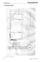
Page 18: ...18 RBM 1305 15 E Version 1 02 Electrical schematic 13 Electrical schematic Fig 17 Electrical schematic RBM 1305 15 E...

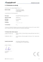
Page 19: ...n the basis of its design and construction as well as the version that we have put into circulation with the relevant fundamental health and safety requirements of subsequent EC guidelines The followi...

Page 20: ...www metallkraft de...

Reviews: