background image

Safety

RBM 1305-15 E | Version 1.02

5

2.4 General safety regulations

Please note the following:

-Use the guards and secure them securely. Never work 

without protections and get them working.

-Always keep the machine and its working environment 

clean. Ensure adequate lighting.

-The bending machine may not be modified in its design 

and may not be used for purposes other than those fore-
seen by the manufacturer.

-Never work under the influence of concentration-distur-

bing illnesses, fatigue, drugs, alcohol or medicines.

- Disconnect power before servicing. If any accessories 

or maintenance are performed on the machine, the 
power supply to the machine must be disconnected 
before carrying out any work.

- Keep children and persons not familiar with the bend-

ing machine away from their work environment.

- Do not pull on the mains lead to pull the plug out of the 

socket. Protect the cable from heat, oil and sharp 
edges.

- Eliminate disturbances that affect safety immediately.

- Never leave the machine unattended.

- Keep the protective device in proper condition. The 

machine must not be operated with removed protec-
tion devices.

- Secure the machine at the ON / OFF switch with a pad-

lock as soon as you leave the work area.

- Protect the round bending machine from moisture.

- Make sure that no parts are damaged before using the 

Bending Machine. Damaged parts must be replaced 
immediately to avoid danger sources.

- Do not overload the bending machine! You work better 

and safer in the specified performance range. Use the 
right tool! Make sure the tools are not dull or damaged.

- Only use original spare parts and accessories to avoid 

possible risks and risks of accidents.

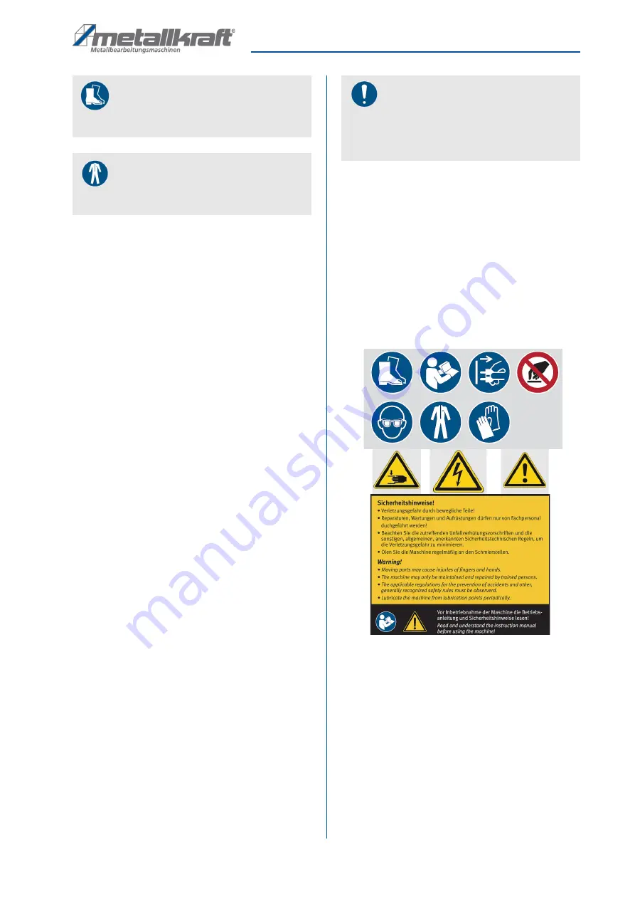
2.5 Safety lables on the machine

The machine has various warning labels and safety 
markings that must be observed and followed. The 
safety markings attached to the bending machine must 
not be removed. Damaged or missing safety markings 
can lead to malfunctions, personal injury and material 
damage. They are to be replaced immediately. 

If the safety markings are not immediately recognizable 
and comprehensible, the round bending machine 
should be taken out of operation until new safety mark-
ings have been made.

Fig. 1:  Safety labels 

Safety boots

Safety boots protect the feet from being crushed, 
falling parts and slipping over on slippery ground. 

Protective clothes

Protective clothes are made of a tightly fitted fabric 
without the protruding parts of low tear strength.

NOTE!

This device should be grounded in accordance with 
national electrical rules and local rules. This must be 
done by a qualified electrician. The machine must be 
earthed to protect the user from electric shock.

Summary of Contents for 3781305

Page 1: ...RBM 1305 15 E Operating Instructions RBM 1305 15 E Bending Machine RBM 1305 15 E...

Page 2: ...t 3 1 2 Customer service 3 1 3 Limitation of liability 3 2 Safety 3 2 1 Symbol explanation 3 2 2 Requirements to staff 4 2 3 Personal protective equipment 4 2 4 General safety regulations 5 2 5 Safety...

Page 3: ...s interested in valuable experience and knowledge gained from using the application which then could be shared and be valuable to develop our products even further 1 3 Limitation of liability All info...

Page 4: ...may only be performed by specialist per sonnel of the manufacturer Other personnel is not au thorized to perform these works Please contact our cus tomer service for the execution of all arising work...

Page 5: ...e round bending machine from moisture Make sure that no parts are damaged before using the Bending Machine Damaged parts must be replaced immediately to avoid danger sources Do not overload the bendin...

Page 6: ...pieces Danger from the ingress of clothing and objects During set up and set up work it may be necessary to dismantle on site protective equipment This creates various residual risks and potential dan...

Page 7: ...collection point for recyclable materials or to the waste disposal company which looks after your region 5 3 Storage Store the bending machine thoroughly cleaned in a dry clean and frost free environ...

Page 8: ...ottom roller Wire insert groove on the top and rear roller 6 2 Safety switch For the safety of the operating personnel the machine is equipped with a safety switch and EMERGENCY STOP brackets When the...

Page 9: ...ers and the motor corresponds to the indicated di rection of the arrow In some cases a reverse connection may cause the motor to burn out It must also be checked whether the direction of rotation of t...

Page 10: ...achine and expose themselves and others to the risk of serious or fatal injuries All work should only be carried out by qualified per sons Keep inadequately qualified persons out of the work area WARN...

Page 11: ...iece from the machine the right hand lock of the upper roller must be released and the upper roller must be removed from the guide Fig 6 Lock of the top roller 8 1 Work process Step 1 Before starting...

Page 12: ...rdboard for the desired radius Always work the workpiece in the center of the rollers Fig 8 Position the workpiece in the middle of the rollers Calculation of the workpiece length Fig 9 Calculation of...

Page 13: ...ng in the material being fed through the machine The hand wheel is equipped with a scale that helps the operator to adjust Bending process Step 1 After adjusting the diameter insert the material on th...

Page 14: ...ne Tips and recommendations To ensure that the bending machine is always in good operating condition regular care and mainte nance work must be carried out DANGER Danger due to insufficient qualificat...

Page 15: ...hus trigger no bending process The rollers are always free from grease and oil Nr Interval lubricants 1 bearing mov able parts monthly oil 2 gears half yearly grease ATTENTION Repair work may only be...

Page 16: ...rvice Indicate the following basic information for requests or orders of spare parts Type of device Item No Position No Year of construction Quantity Required mode of dispatch mail freight sea air exp...

Page 17: ...pare parts drawing In case of service the following drawing shall help to identify the necessary spare parts If necessary send a copy of the parts drawing with the marked components to your authorized...

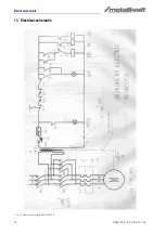
Page 18: ...18 RBM 1305 15 E Version 1 02 Electrical schematic 13 Electrical schematic Fig 17 Electrical schematic RBM 1305 15 E...

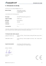
Page 19: ...n the basis of its design and construction as well as the version that we have put into circulation with the relevant fundamental health and safety requirements of subsequent EC guidelines The followi...

Page 20: ...www metallkraft de...

Reviews: