8
RBM 1305-15 E | Version 1.02
Description of the device
6
Description of the device
Illustrations in this operating manual serve the general under-
standing and may deviate from the actual design.
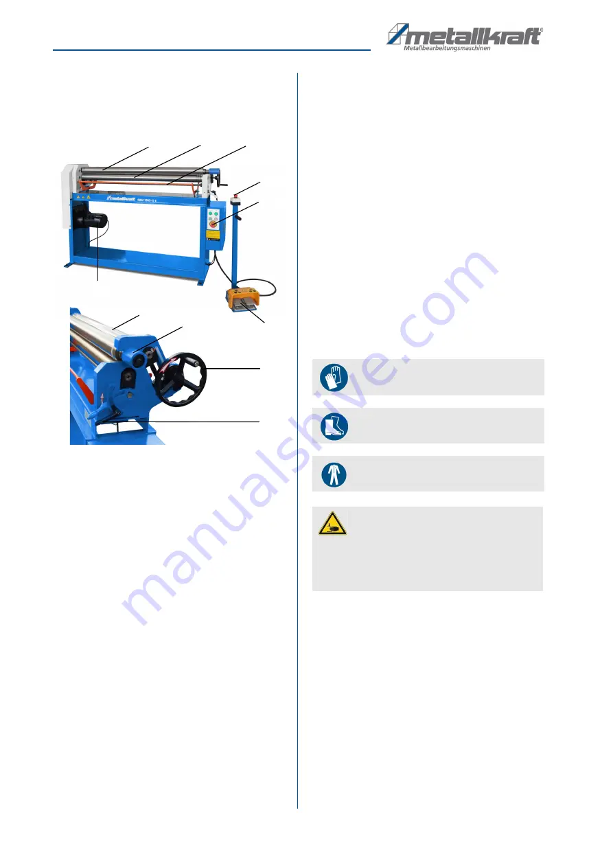
Fig. 4: Controls
1 Top roller folds out
2 Bottom roller
3 EMERGENCY brackets
4 EMERGENCY STOP button
5 Pedals:
right pedal direction of rotation right,
left pedal direction of rotation left
6 Hand wheel for adjusting the rear roller
7 Clamping lever
9 Locking the top roller
10 Behind roller
11 Drive motor
Control panel with pedals
The control panel is equipped with an EMERGENCY
STOP button, which immediately interrupts all machine
movements when disconnected from the power con-
nection until it is released.
Function of the pedals:
right pedal: Direction of rotation.
left pedal: Direction of rotation.
6.1 Scope of delivery
The scope of delivery of the machine includes:
- Driven Top and bottom roller
- Wire insert groove on the top and rear roller
6.2 Safety switch
For the safety of the operating personnel, the machine is
equipped with a safety switch and EMERGENCY STOP
brackets.
When the EMERGENCY STOP brackets is actuated, the
safety switch is activated as with EMERGENCY STOP,
which stops all machine activities.
7
Installation and connection
7.1 Installation
To achieve good functionality and long life of the Bend-
ing Machine, the site should meet the following criteria:
- The substrate must be level, firm and vibration-
free.
- The installation or work area must be dry and well
ventilated.
- Do not operate machines that cause dust and
chips near by.
- There must be sufficient space for the operating
personnel, for material transport as well as for ad-
justment and maintenance work.
- The site must have good lighting.
1
2
4
3
4
5
6
9
10
11
7
Wear safety gloves!
Wear safety shoes!
Wear protective clothing!
CAUTION!
Risk of crushing!
The bending machine can tilt when setting up and
cause serious injuries.
- The round bending machine must be set up by at
least 2 people together.


