background image

Setting up

AKM-Series 220 | Version 1.07

11

7 Setting up

7.1 Place of installation

In order to ensure good functioning of the notching ma-
chine and a long service life, the installation site should 
meet the following criteria.

- The notching machine may only be installed and 

operated in dry, frost-free, well-ventilated rooms. 

- Avoid places near machines that cause chips or 

dust. 

- The place of installation must be vibration-free, i.e. 

away from presses, planing machines, etc. 

- The ground must be suitable for the work. Pay atten-

tion to the bearing capacity and evenness of the 
ground. 

- If necessary, protruding parts, such as support ta-

bles, etc., must be secured by on-site measures so 
that persons are not endangered.

- Provide sufficient space for set-up and operating 

personnel and material transport. 

- Also consider accessibility for adjustment and 

maintenance work. 

- Provide adequate lighting (minimum value: 300 lux).
- The humidity should be in the range of 10% to 90% 

and the measured room temperature should be bet-
ween max. 0°C - 50°C.

Setting up the machine:

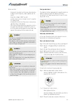
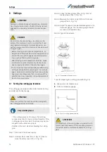
Step 1: Make sure that the space around the machine is 

sufficient for the application (Fig. 8). There must 
be sufficient space for the operator and material 
transport.

Step 2: Check each part of the machine for proper con-

dition before starting to set it up.

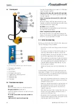
Step 3: Place the control foot pedal in the best position 

for the application in front of the work area.

Fig. 8: Setup plan

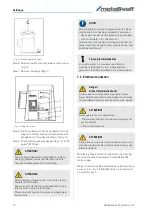
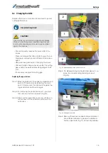
Step 4: Remove the hexagonal head cap screws 85 

(Fig.9).

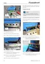
Step 5: Use a crane to lift the machine from the pallet 

and move it to the working position (Fig.10).

Fig. 9: Removing the fixing screws 

ATTENTION!

Check the load-bearing capacity of the ground 
before you install the machine. The installation place 
must be capatable of bearing the weight of the 
machine and the workpieces.

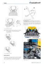
ATTENTION!

The machine is delivered unfilled. Before commis-
sioning, hydraulic oil must be filled into the tank.
Only use suitable hydraulic oil for refilling.

Stock area of 
cutted material 

Free clearance 

space

Stock area of material 
which will be cut

Free space for operation and 

material feed/removal

Required minimum width

R

equi

re

mi

nim

um

 depth

Summary of Contents for 3834200

Page 1: ...AKM 220 4 H Operating Instructions AKM 220 4 H AKM S ERIES Hydraulic Notching Machine AKM 220 6 H AKM 220 6 H ...

Page 2: ...ns 5 2 6 Safety labels on the machine 6 2 7 Safety devices 6 3 Intended Use 7 3 1 Improper use 7 3 2 Residual risks 7 4 Technical Data 8 4 1 Table 8 4 2 Type plates 8 5 Transport packaging storage 9 5 1 Delivery and transport 9 5 2 Packaging 10 5 3 Storage 10 6 Description of device 10 6 1 Representation 10 6 2 Scope of delivery 10 6 3 Accessories 10 7 Setting up 11 7 1 Place of installation 11 7 ...

Page 3: ...de We are always interested in valuable experience and knowledge gained from using the application which then could be shared and be valuable to develop our products even further 1 3 Limitation of liability All information and notes in these operating instructions were summarised taking the applicable standards and rules the state of the art and our long term knowledge and experiences into conside...

Page 4: ...n regular intervals and in form them about the hazards The operator must provide the necessary protec tive equipment to the staff and order the use of the neces sary protective equipment in a binding way Furthermore the operating company is responsible to keep the notching machine always in a technically flaw less state Thus the following applies The operator must ensure that the maintenance in te...

Page 5: ...hting Always secure your workpiece when working with suitable clamping devices Ensure a sufficient con tact surface Check that the fixed hand guards are correctly instal led The design of the notching machine must not be changed and it must not be used for purposes other than those foreseen by the manufacturer Never work under the influence of illnesses that im pair concentration drugs alcohol or ...

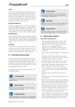
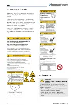
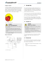
Page 6: ...e replaced immediately The machine must be taken out of operation until the new labels are attached as soon as the labels are not immediately recognisable and comprehensible at first sight Fig 1 Safety labels 2 7 Safety devices WARNING Danger to life due to non functioning safety devices If the safety devices are not functioning or have been rendered inoperative there is a risk of serious injury o...

Page 7: ...age due to improper use are excluded 3 1 Improper use The notching machine must not be used for notching materials made of light metals e g aluminium or similar 3 2 Residual risks Even if all safety instructions are observed and the ma chine is put to its intended use there are still residual risks which are listed below Risk of injury of upper limbs while equipment is ope rating Danger from the f...

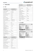
Page 8: ...N mm 2 mm Oil tank capacity 22l Sound pressure level opera tion 1m distance 70 dB Sound pressure level no load 1m distance 62 dB Weight 375 kg Technical Data Model AKM 220 6 H Dimensions LxBxH max 860x860x1100mm Working pressure 145 bar Motor output 3 kW Total power consumption 8 A Electrical voltage 400 V Phase s 3 Ph Mains frequency 50 Hz Max cutting pressure 24 t Cutting area LxB 220mmx220mm Wo...

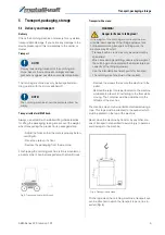
Page 9: ...falling to the floor while moving The container must be positioned on the left side of the machine The machine may only be loaded and unloaded using a rope This rope must be attached to the eyebolt which must be placed on the top of the machine Never move the machine by hand or by any other me ans of transport not specified to avoid injury to persons and damage to the machine Fig 6 Transport with ...

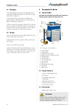
Page 10: ... a suitable place e g pro tected and not exposed to bad weather If the machine is to be taken out of operation for a short period of time clean it thoroughly and cover it with a cloth 6 Description of device 6 1 Representation Illustrations in these operating instructions are for basic under standing only and may differ from the actual version Fig 7 Description of device AKM 220 4 1 Punching tool ...

Page 11: ...ed room temperature should be bet ween max 0 C 50 C Setting up the machine Step 1 Make sure that the space around the machine is sufficient for the application Fig 8 There must be sufficient space for the operator and material transport Step 2 Check each part of the machine for proper con dition before starting to set it up Step 3 Place the control foot pedal in the best position for the applicati...

Page 12: ... foot pedal Never use your hands or any available aids to ope rate the machine via the foot pedal This will prevent injuries to persons and damage to the machine NOTE After installation remove the grease from the blank metal parts which has been applied for protection Use common solvent for this purpose e g petroleum Do not use water nitro solvents etc After the machine has been thoroughly cleaned...

Page 13: ...in the wrong direction Step 1 When equipped with a phase inverter Use a screwdriver to push in the washer in the plug and turn it by 180 Fig 12 Change motor direction of rotation Without phase inverter Have two phases at the electrical connection re placed by a qualified electrician Step 2 Check the direction of rotation of the motor WARNING This device is equipped with a protective conductor and ...

Page 14: ... acting machine elements may only be carried out on the machine by trained specialists or specially trained and instructed per sons DANGER Incorrect mechanical settings can influence the safety of the machine to such an extent that it cau ses a permanent danger Careless behaviour can put the personnel and the machine at risk when swit ching on again Before making any mechanical adjustments al ways...

Page 15: ...ain switch Now secure the main switch against be ing accidentally switched on again Step 2 For removing the protective cover 1 you must first unscrew the three screws 2 Fig 15 Step 3 Dismount the protective cover now Lift the pro tective cover off the cutter bar and store it in a safe place Fig 15 Disassembling of the protective cover Step 4 For disassembling the downholder device 3 un screw the c...

Page 16: ... in contact with each other Replacing the lower knives First perform steps 1 to 8 of the section Replacing the upper knives First disassemble only one upper knife Then continue with step 9 in the Replacing the lower knives section Fig 19 Access to the fixing screws of the lower knife Step 9 After the upper knife has been removed you can use an Allen key to reach the screws of the adjacent lower kn...

Page 17: ...tting the limit stops Adjustable stops are used to limit or guide the process ing of the sheets Step 1 Move the cutter bar to the upper end position and switch off the machine by pressing the main switch Now secure the main switch against ac cidental restarting Step 2 Set the currently required stops according to the following information Use the setting examples as a basis for the cur rently requ...

Page 18: ...A of the angle stops can be moved across the T slot The angle of the stop bar to the measuring tape is adjusted via the grid plate B angle wheel Fig 26 Adjustment elements The clamping lever C Fig 26 is used to fix the current set ting The measuring tapes embedded in the table are each provided with an outer and inner scale The outer and inner scales are each inclined by 45 to allow precise adjust...

Page 19: ...ong hair DANGER Risk of injury There is a risk of injury to the upper limbs e g hands fingers ATTENTION Never step on the foot pedal if You have connected the electrical supply and the air pressure supply You want to start the application during operation You have completed a started maintenance ATTENTION Never change the settings for the hydraulic system This is especially true for valves present...

Page 20: ...eft 9 3 Initial commissioning Before you start the machine for the first time make sure that the following points are fulfilled The machine is anchored to the ground at the instal lation site The direction of rotation of the motor has been suc cessfully checked after connection to the mains Enough hydraulic oil has been filled into the oil tank to reach the upper level at the oil sight glass The h...

Page 21: ... 5 Shut down the machine Step 1 Turn off the main switch Step 2 Disconnect the power plug 10 Maintenance and repair Tips and recommendations Before starting the production make a few test cuts Tips and recommendations To keep the notching machine in a good operating condition regular care and maintenance work must be carried out WARNING Danger from the insufficient qualification of persons Insuffi...

Page 22: ...aulic oil tank Carry out the check daily during the first week after initial commissioning A weekly check is then required DANGER When carrying out care maintenance and repair work pay attention to protruding parts in order to avoid injuries DANGER When carrying out maintenance and repair work ensure that the compressed air supply hose is dis connected and that the safety device is connected to th...

Page 23: ...e that the oil drain plug is properly inserted and tightened before fil ling the hydraulic oil If the hydraulic oil is to be replaced place an oil tray under the oil drain plug When selecting the oil tray ensure that there is a maximum of 36 litres of oil in the oil tank When filling make sure that the hydraulic oil does not run to the ground and that there is a danger point Use a funnel as a prev...

Page 24: ...pment Please note that electrical devices contain a variety of recyclable materials as well as environmentally harmful components You contributes to that these components are disposed of separately and properly In case of doubt please contact your municipal waste disposal As necessary a specialized waste disposal company can help be used for the treatment 11 3 Disposal of lubricants Please pay att...

Page 25: ... the control panel are functionless Start light is off 1 Emergency stop button has been actuated 2 The motor protection switch was triggered 1 Unlock the emergency stop button 2 Have check by a qualified electrician Upper knife does not react to a buttons actuations in the manual mode 1 Selector switch for manual foot op eration on the control panel is de fect 1 Have check by a qualified electrici...

Page 26: ...pe plate The type plate is mounted on the device Example The guide pillar for the AKM 220 4 H must be ordered The guide pillar has the number 31 in the spare parts drawing By ordering spare parts send a copy of spare parts drawing with marked part guide pillar and marked po sition number 31 to the dealer or spare parts depart ment and provide the following information Type of device Hydraulic Notc...

Page 27: ...gs In case of the service the following drawings shall help to identify the necessary spare parts If necessary send a copy of the parts drawing with the marked components to your dealer Spare parts drawing AKM 220 4 H Fig 32 Spare parts drawing AKM 220 4 H AKM 220 4 H ...

Page 28: ...28 AKM Series 220 Version 1 07 Sparte parts Spare parts drawing AKM 220 6 H Fig 33 Spare parts drawing AKM 220 6 H AKM 220 6 H ...

Page 29: ... diagrams AKM Series 220 Version 1 07 29 14 Wiring diagrams 14 1 Electrical circuit diagrams Fig 34 Electrical circuit diagram AKM 220 4 H Fig 35 Electrical circuit diagram AKM 220 6 H AKM 220 4 H AKM 220 6 H ...

Page 30: ...30 AKM Series 220 Version 1 07 Wiring diagrams 14 2 Hydraulic circuit diagram Fig 36 Hydraulic circuit diagram AKM 220 4 H and AKM 220 6 H ...

Page 31: ...elevant provisions of the above mentioned directive as well as the other applied directives below including their applicable modifications at the time of the declaration Relevant EU Directives 2014 30 EU EMC Directive The following harmonised standards have been applied DIN EN ISO 12100 2010 Safety of machinery General principles for design Risk assessment and risk reduction DIN EN 60204 1 2014 10...

Page 32: ...www metallkraft de ...

Reviews: