18
AKM-Series 220 | Version 1.07
Settings
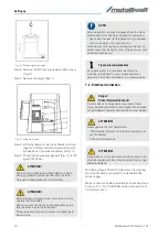
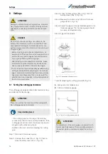
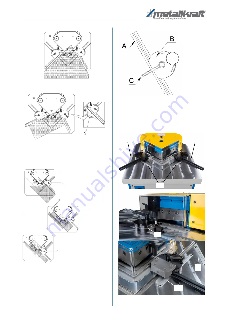
Fig. 24: Setting the limit stops
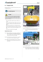
Step 5: Adjust the left and right stops (Pos. 8, Fig.23) to
fit the workpiece to the working reference
(Fig.24 and 25).
Fig. 25: Setting the limit stops
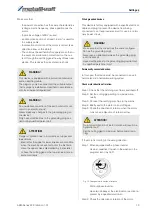
Adjustment elements
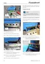
The stop bar A of the angle stops can be moved across
the T-slot. The angle of the stop bar to the measuring
tape is adjusted via the grid plate B (angle wheel).
Fig. 26: Adjustment elements
The clamping lever C
(Fig. 26) is used to fix the current set-
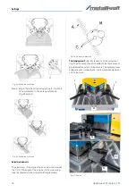
ting. The measuring tapes embedded in the table are each
provided with an outer and inner scale. The outer and inner
scales are each inclined by 45° to allow precise adjustment
of the stop bars.
Fig. 27: Scales
E
E
D
E
B
A
D
Summary of Contents for 3834200
Page 32: ...www metallkraft de ...


