background image

Settings and commissioning

HKS 230 | Version 3.06

9

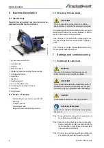
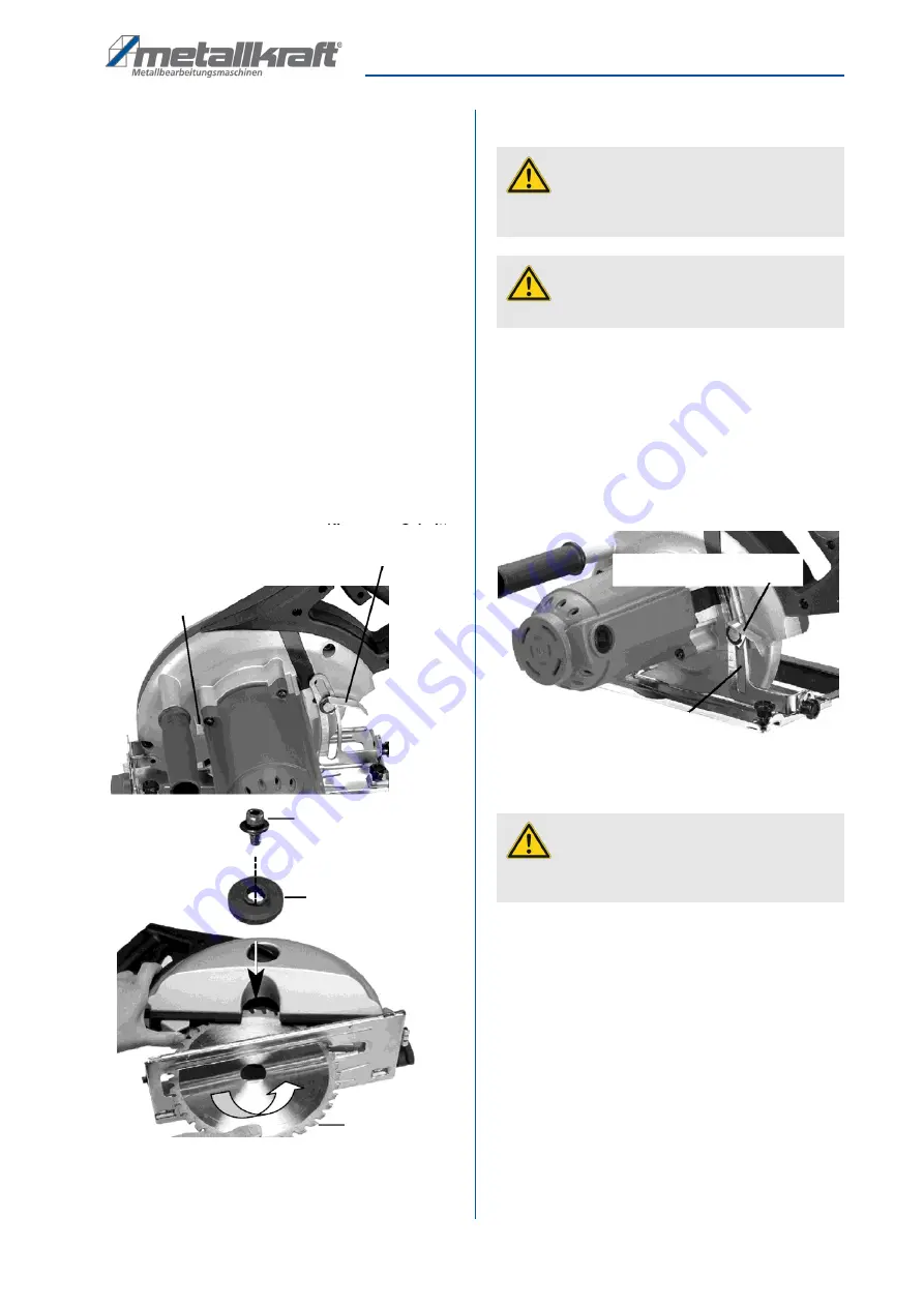
Step 4: Wearing protective gloves, remove the saw 

blade and insert the new blade in its place on the 
contact flange. Make sure that the teeth are 
pointing forwards. In case of doubt, check the di-
rectional display printed on the saw blade. 

Step 5: Position the outer saw blade flange with the flat 

side facing the saw blade; then fit the fastening 
screw and hand-tighten (Fig. 3). 

Step 6: Use a hexagon socket wrench to turn the fasten-

ing screw clockwise. Press the saw blade lock 
while doing so, and turn the saw blade support 
with the wrench until you notice it engage. 

Step 7: After the saw blade lock has engaged, tighten 

the fastening screw to final torque by turning 
clockwise.

Step 8: Before operating the saw, make sure that the 

saw blade lock is back in its original position.

Fig. 4: Saw blade assembly

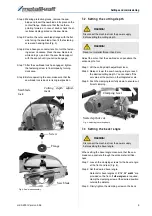
7.2 Setting the cutting depth

Adjust the cut so that the saw blade can penetrate the 
entire depth of cut.

Step 1: Lift the cutting depth adjustment lever. 

Step 2: Raise or lower the saw housing until you reach 

the desired cutting depth. You can read off the 
set value at the pointer on the integrated scale. 

Step 3: Push the clamping lever fully down to ensure suf-

ficient clamping.

Fig. 5: Adjusting the cutting depth

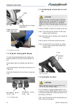
7.3 Setting the bevel angle

When setting the bevel angle make sure that the saw 
blade can penetrate through the entire material thick-
ness. 

Step 1: Loosen the clamping screws for the bevel angle 

at the front and rear (Fig. 6). 

Step 2: Set the desired bevel angle. 

Detents for bevel angles of 

0°, 15°, 30° and 45°

 are 

provided on the front. If 

other angles

 are required, 

clamp the clamping screw at the desired position 
outside the detents.

Step 3: Firmly tighten the clamping screw on the back.

Saw blade

Screw

Flange

Sawblade
lock

Cutting depth adjust-
ment

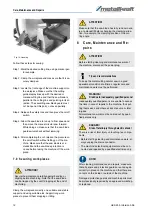
WARNING!

Disconnect the machine from the power supply 
before setting the cutting depth.

WARNING!

Never cut material thicker than 9 mm

WARNING!

Disconnect the machine from the power supply 
before setting the bevel angle.

Clamping lever

Scale depth of cut

Summary of Contents for 3840231

Page 1: ...HKS 230 Instruction Manual HKS 230 HKS 230 Metal cutting manual circular...

Page 2: ...rcular saw 6 2 7 Safety data sheets 6 3 Intended Use 6 3 1 Reasonably foreseeable misuse 6 3 2 Residual risks 6 4 Technical Data 7 4 1 Table 7 4 2 Type plate 7 5 Transport packaging storage 7 5 1 Deli...

Page 3: ...you with specialist advice and information Germany St rmer Maschinen GmbH Dr Robert Pfleger Str 26 D 96103 Hallstadt Germany Repair service Fax 49 0 951 96555 111 email service stuermer maschinen de...

Page 4: ...required protec tive equipment shall be mandatory Operators shall also be responsible for maintaining the machine in a technically perfect condition For this rea son the following shall apply Operator...

Page 5: ...ur work environment clean at all times Ensure sufficient illumination Always secure the workpiece when working Ensure a sufficient support surface The metal cutting circular saw s design must not be c...

Page 6: ...Use of the metal hand held circular saw for materi als other than aluminium PVC or wood materials e g machining of hard metal or similar plastic etc Modifications to the machine or accessories Mainte...

Page 7: ...ste disposal company 5 3 Storage Always store the metal cutting circular saw in a clean condition and a dry clean and frost free environment It must not be stored in the same room as chemicals Dur ing...

Page 8: ...material cannot be easily taken up by the gullet If the TPI value is too high the saw teeth starts to chop this can lead to teeth breaking out 7 Settings and commissioning 7 1 Installing the saw blad...

Page 9: ...te the entire depth of cut Step 1 Lift the cutting depth adjustment lever Step 2 Raise or lower the saw housing until you reach the desired cutting depth You can read off the set value at the pointer...

Page 10: ...tart the machine Step 4 To switch off the manual circular saw release the on off switch and allow to snap back to its original position Fig 8 On off switch 7 6 Setting the rip fence For cuts parallel...

Page 11: ...ing or not working correctly is prohibited Immediately hand over machines with a saw blade malfunction for repair to an authorised or qualified workshop ATTENTION Before using the manual circular saw...

Page 12: ...e carefully against bending or slipping before machining Note that the saw blade can be trapped by the cut off dropping at the end of machining ATTENTION Make sure that the saw blade has fully run dow...

Page 13: ...8 3 Changing the power supply cable ATTENTION Never use solvents for cleaning plastic parts or painted surfaces This may cause the surface to disintegrate and cause consequential damage ATTENTION All...

Page 14: ...sposal compa nies Disposal notes for used lubricants are available from the manufacturer of the lubricants If necessary re quest the product specific data sheets 10 Spare Parts 10 1Ordering spare part...

Page 15: ...pare parts drawing HKS 230 The following drawing is intended to identify the required spare parts in the event of service If applicable submit a copy of the parts drawing including the highlighted com...

Page 16: ...shaft M1 25x9T 1 28 Panhead tapping screw b M5x25 2 29 Panhead tapping screw b M5x30 2 30 Gear housing 1 31 Panhead machine screw Washer M5x25xP0 8 1 32 Ball bearing 6001 1 33 Armatur 220V 73x42x45 1...

Page 17: ...evel washer 10 1x 14x1 2 1 82 Safety belt 1 84 Wire lead 1015 16 18CM 2 85 Female spade terminal 4 86 Spade terminal boot 6 87 Crimp cab connector C4 1 88 Zip tie 2 5x100MM 1 92 O Ring 12x4 1 93 E Cli...

Page 18: ...any other applicable directives subse quently added including the changes applicable at the time the declaration was made Applicable EU directives 2014 30 EU EMC Directive The following harmonised st...

Page 19: ...Notes HKS 230 Version 3 06 19 12 Notes...

Page 20: ...www metallkraft de...

Reviews: