10
HKS 320 | Version 1.04
Description of the device
6 Description of the device
6.1 Presentation
Illustrations in these operating instructions are for basic un-
derstanding and may differ from the actual design.
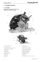
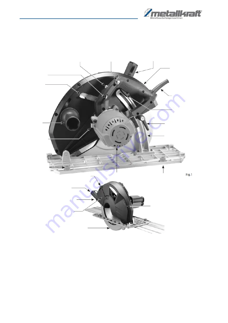
Fig. 3: Description of the HKS 320
1 Load indicator lamp
2 Release button of the locking device
3 Vacuum cleaner connection
4 Main handle
5 Power cable
6 Release switch
7 Depth locking lever
8 Depth scale
9 Base plate
10 Motor unit
11 Clip switch
12 Dust connection cap
13 Vacuum cleaner connection
14 Cover of the dust chamber
15 Lower saw blade protection
16 Upper saw blade guard
17 Guide play adjusters
18 Mandrel locking lever
19 Side handle
20 Kicker lever
21 L-hexagon key stored in the main handle
1
2
3
4
21
5
6
7
8
9
10
11
12
13
14
15
16
17
18
19
20

