background image

10

GS 18 | Version 1.05

Operation

7.3 Drilling

Step 1: Place the tap on the workpiece and position the 

machine so that the tap is accurately centered 
on the center of the core hole.

Step 2: Press the machine onto the workpiece to set the 

rotation direction for screwing in. 

Step 3: Start the machine by pressing and holding the 

ON switch.

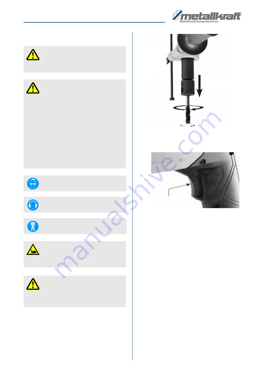
Fig. 6: ON- / OFF-Switch

Step 4: Make sure that the tap is exactly in line with the 

core hole, during the entire cutting process.

Step 5: When the desired depth of cut has been 

reached, release the On button. The machine 
halts.

Step 6: Pull the machine backwards to set the direction 

of rotation to bore and restart the machine by 
pressing and holding the on switch until the tap 
is removed from the core hole.

ATTENTION!

Never use a tool with larger dimensions than 
approved by the manufacturer.

ATTENTION!

-  Make sure that the workpiece is not under pressure 

before each cutting operation.

-  Check that the machine has been aligned exactly 

to the core hole.

-  Only cut with sharp tools!
-  Remove chips regularly to avoid large amounts of 

chips. This could damage the tool.

-  The tool and the cutting residue are very hot at the 

end of the cutting process. Do not touch, risk of 
burns!

-  When cutting, always apply cutting oil to the tool by 

hand!

Wear eye protection!

Wear ear protection!

Wear protective clothing!

CAUTION!
Risk of crushing!

Improper work with the tap can result in injury to the 
upper limbs.

ATTENTION!

This machine is designed exclusively for cutting 
right-hand threads. Left-hand threads are not possi-
ble with this machine!

Downforce:
Clockwise

ON- / OFF-Switch

Summary of Contents for 3860018

Page 1: ...GS 18 Operating Instructions GS 18 Tapping Power Tool GS 18...

Page 2: ...t 3 1 2 Customer service 3 1 3 Limitation of liability 3 2 Intended use 3 3 Safety 4 3 1 Symbol explanation 4 3 2 Obligations of the operating company 4 3 3 Requirements to staff 5 3 4 Personal protec...

Page 3: ...9 E Mail ersatzteile stuermer maschinen de We are always interested in valuable experience and knowledge gained from using the application which then could be shared and be valuable to develop our pro...

Page 4: ...ronment protection regulations applying for the area of application of the machine must be met The following applies in particular The operating company must be informed about the applying industrial...

Page 5: ...ied personnel Due to their professional training knowledge and expe rience as well as their knowledge of relevant regulations the specialist staff is able to perform the assigned tasks and to recogniz...

Page 6: ...h them with your bare hands Re move these with a magnetic chip collector or a chip hook Remove metal chips only when the ma chine is switched off 3 8 Residual risks Even if all safety regulations are...

Page 7: ...ycling depot to be disposed of The delivery packaging is made of cardboard so please dispose carefully by having it chopped up and given to the recycling collection The film is made of polyethylene PE...

Page 8: ...the ac tual design Fig 3 Description Tapping Power Tool GS 18 1 Locking screw 2 Turning head 3 Locking screw 4 Depth stop 5 Housing 6 Motor 7 Handle 8 ON Schwitch 9 Side handle 10 Safety friction clu...

Page 9: ...is off Step 2 Plug in the mains plug into the 230V socket after clamping the tool ATTENTION Make sure that the workpiece is not under pressure before each cutting operation Check that the workpiece i...

Page 10: ...h until the tap is removed from the core hole ATTENTION Never use a tool with larger dimensions than approved by the manufacturer ATTENTION Make sure that the workpiece is not under pressure before ea...

Page 11: ...tapping power tool is always in good operating condition regular care and mainte nance work must be carried out WARNING Danger due to insufficient qualification of persons Insufficiently qualified pe...

Page 12: ...they are worn Fig 7 Carbon brushes Fig 8 Change carbon brush Step 1 Unscrew the four engine cover screws and re move the engine cover Step 2 Use needle nose pliers to push the spring aside Step 3 Unsc...

Page 13: ...urer If neces sary ask for the productspecific data sheets 10 Spare parts 10 1 Ordering spare parts The spare parts can be obtained from the dealer or di rectly from the manufacturer The contact detai...

Page 14: ...art drawing Type of device Tapping Power Tool GS 18 Item number 3860018 Position number 14 The order number is 0 3860018 14 The order No consists of the item No 3860018 the po sition No 14 and one dig...

Page 15: ...11 Spare part drawing In case of service the following drawing shall help to identify the necessary spare parts If necessary send a copy of the parts drawing with the marked components to your authori...

Page 16: ...16 GS 18 Version 1 05 Electrical wiring diagram 12 Electrical wiring diagram Fig 10 Electrical wiring diagram GS 18...

Page 17: ...nto circulation with the relevant fundamental health and safety requirements of subsequent EC guidelines Relevant EU directives 2014 30 EU EMC Directive 2011 65 EU RoHS Directive The following harmoni...

Page 18: ...www metallkraft de...

Reviews: