20
GS-E Series | Version 1.09
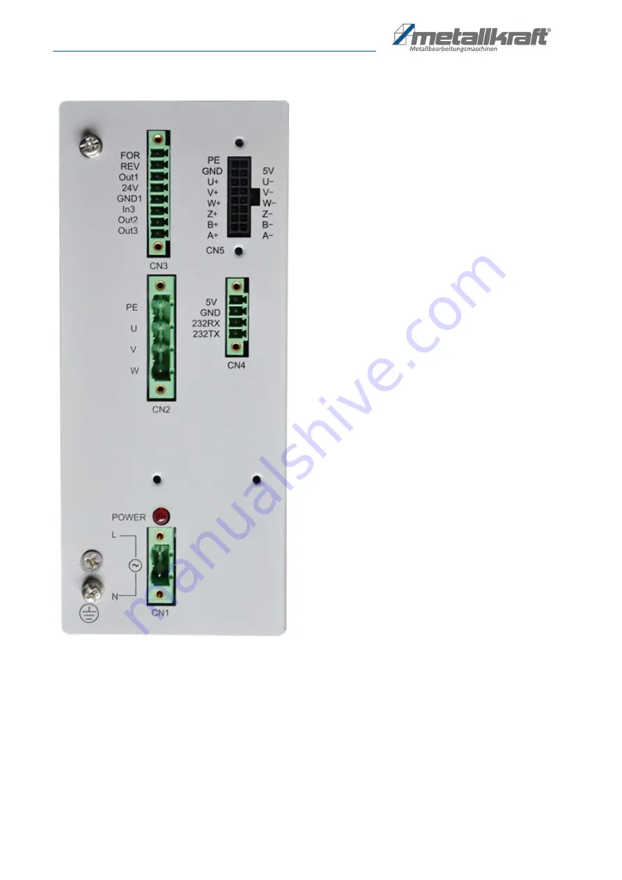
Wiring Diagram Control Unit
13 Wiring Diagram Control Unit
Fig. 21: Wiring Diagram Control Unit
FOR
Motor possitive transmission
REV
Motor reversal
Out1
Set output standby 1, function according to customer requirments
24V
Power supply 24V/250mA
GND1
Power 0V
In3
Input standby 1, set the function according to customer requirements
Out 2
Set output standy 2, function according to customer requirements
Out 3
Set output standby 3, function according to customer requirements
CN1 terminal:
L,N as 220VAC power input.
CN2 terminal:
Power line of servo motor. (note the direction of
the plug)
CN3 terminal
: Handle control direction line, FOR terminal is
connect for start and forward direction,REV termi-
nal is for reverse direction,and the GND1 is
connected to the COM (for the public ground).
CN4 terminal:
LCD touch screen control line.
CN5 terminal:
Encoder line of servo motor.
Summary of Contents for 4450116
Page 22: ...www metallkraft de ...


