background image

- 1 - 


GENERAL NOTES 

1. Introduction 


Thank you for choosing a METALLKRAFT Metal Working Machine. We are proud to have you 

in our long list of satisfied customers all over the world. 


This User’s Manual is absolutely for your safety and is essential for the machine to have a  

long production life. As long as you keep up with our Manual you will be able to run your machine 
smoothly and safely. Keep in mind that the machine is designed absolutely to perform maximum  
safety and for efficient working. 


In this Manual you can find instructions and information about: 


Correct installations of the machine 


Description of the functional parts of the machine 


Set-up and start-up adjustments 


Correct standard and scheduled maintenance 


Simple safety regulations and accident prevention. 


Therefore, as far as the user’s safety is concerned, in this handbook the possible risks con- 

nected with machine operation are pointed out as follows: 


Attention:  Showing the risks of accident, if instructions are not followed. 


Warring: Showing the probable damages to the machine or equipment, if the 
instructions are not strictly followed. 


Note:  It gives useful information. 


It is certainly necessary that the operator should read and understand all the Attention

Warring, 

Note specified in this Manual before starting with operation of the machine and before any 

lubrication or maintenance intervention 

On all steps of installation, operation and maintenance safety must be your first concern for 

the protection of yourself, other users and the service of the machine. In case of any failure please first 
refer to this Manual, and then if a solution cannot be found contact first of all the distributor where you 
purchased our product. Do not forget to refer to the drawings and the numbers for any spare part 
needed or to define any problem. Make sure you have the serial number and production year of the 
machine. 


Our technical staff will make their best to help you in the most convenient way. 


Summary of Contents for HPS 115 DS

Page 1: ...Operating Instructions Hydraulic section steel shears HPS 55 DS HPS 65 DS HPS 85 DS HPS 115 DS HPS 175 DS HPS DS Series...

Page 2: ...rk stations 19 Angle cutting installation 20 Mitring angle 45 degrees 21 Profie cutting station 22 Shearing profile section cutting 23 Notching station 24 Stroke adjustment 25 Hydraulic system 26 27 M...

Page 3: ...hine operation are pointed out as follows Attention Showing the risks of accident if instructions are notfollowed Warring Showing the probable damages to the machine or equipment if the instructions a...

Page 4: ...edures and fully understanding the drawings For any unclear matters get in touch with St rmer Maschinen GmbH Have the machine connected by a qualified electric technician For as we made clear in the g...

Page 5: ...e adjustment of the shear levers should be carried out before any adjustment of the shear blade The adjustment explain as shown below Explanation of figure 1 Adjustment screw 2 Safety nut 3 Bronze pre...

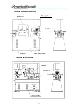
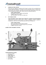
Page 6: ...4 Punch unit Punch cylinder Punch unit Driver set hydraulic VIEW OF THE DELIVERY SIDE Lever group VIEW OF THE EXIT SIDE...

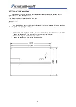
Page 7: ...structions For an effective machine the position and the base of the machine are important Be careful on these points while placing the machine The machine must be placed on a flat preferably cement b...

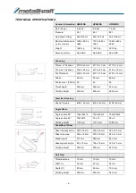
Page 8: ...ickness max 200 x 20 mm 300 x 20 mm 380 x 20 mm Sheet size max 300 x 15 mm 375 x 15 mm 480 x 15 mm Blade lenght 317 mm 380 mm 482 mm Shearing with angle 80 x 15 mm 100 x 15 mm 120 x 15 mm Working heig...

Page 9: ...10 100 x 100 x 10 100 x 100 x 13 V bending Press brake Bar bend max 250 x 12 mm 250 x 15 mm 250 x 20 mm Sheet bend max 500 x 3 mm 500 x 3 mm 500 x 4 mm Punching on notcher Bar bend max 125 mm 125 mm 1...

Page 10: ...mm 16 mm Width L 60 mm 60 mm Depth P 100 mm 100 mm Working height 935 mm 910 mm Optional Tools HPS115DS HPS175DS U I Section blades 200 x 90 mm 300 x 125 mm T Section blades 120 x 13 mm 150 x 15 mm V...

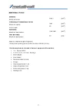
Page 11: ...gth 45 kg mm2 The maximum punching pressure of this machine is 650 kN 65 ton 500x3 mm2 38x8 mm2 85 mm2 100x100x6 mm3 83 mm The following tools are included in the basic equipment of the machine 1 C Sp...

Page 12: ...er shut the main switch never leave the machine unattended do NOT overload the machine 2 SHEARING STATION The shearing unit has been equipped with a simple and robust fixing installation which can be...

Page 13: ...or a better work 5 NOTCHING STATION The notching station has been equipped as standard with a rectangle unit and threading table having adjustable counter holders which enable a repeatable positioning...

Page 14: ...The most dangerous and probable deviations as to the construction limits of the machine are estimated to be as follows 1 Machining of other materials as unalloyed steel 45kg mm2 2 Erroneous use of th...

Page 15: ...eaks 6 Never punch any material which stronger than the diameter of the hole stamp In this case the hole stamp can be overloaded and easily break 7 Always punch trough holes Never punch base holes unl...

Page 16: ...der to start the machine In order to ensure this make sure that the red off button STOP rotates clockwise or directly todraw 2 Make sure that the entries for hole stamp and cutting case are safetyfixe...

Page 17: ...unching position Nevertheless the machine doesn t turn back to the standby position until the pedal is left loose The central pedal position allows the operator to effect unlimited positioning includi...

Page 18: ...ed on the machined surface of the matrix In order to allow a suitable play area and to ensure that the material is taken out the punch stamp scraper plate should be correctly adjusted however it shoul...

Page 19: ...orrectly fixed 5 Connect the machine and than position at adjustment 6 Move the hole stamp slowly towards the cutting case Push the cutting case delivery plate correctly so that the hole stamp and cut...

Page 20: ...E P D S TRANTION RESISTANCE A calculation example A 20 mm hole will be necessary in a 12 mm thick homogenous steel sheet metal having 45kg mm2 traction resistance This is valid the following Punching...

Page 21: ...holder Wrong sized part Wrong distance Normal punching Very small punching which requires special eccentric die and tool FLANGE PUNCHING You can use the standard tool for all kind of punching however...

Page 22: ...mountain 450 at verticalposition Now place the other and in the blade here the left support position is used and then cut the material longitudinally For this purpose 450 should be maintained for fro...

Page 23: ...the operation cutting angle in the angle cutting station requires the following simple hold down adjustment Once the hold down is secured for cutting as position 3 it is also possible use the hold dow...

Page 24: ...des together with the soc head cap bolts Nr 1 totally onto the shear lever In order the adjust the blades more the shear lever so wide towards down that both blades get aligned Now disconnect the mach...

Page 25: ...al or the cutting of flange of angle profiles which have been previously cut at the inclined cutting station Always place the material from the entry side of the machine and make sure that the materia...

Page 26: ...uld be followed for the change of the notching threading blade set 1 Move the stamp to the exit position that means fully open 2 Disconnect the machine at the main switch 3 Remove the scraper finger a...

Page 27: ...can also be carried out by using the leading mode For this purpose the punch and or shear position is arranged in such a manner that the required position is obtained by the foot pedal and then the s...

Page 28: ...the lower machine body protection the section located under the main chassis should be checked each year for dirt and impurities Cleaning Under normal operation conditions all the visible working par...

Page 29: ...en operated and that there is oil pressure indicated check oil level in pump HYDRAULIC OIL LIST On most of our machines hydraulic systems we use Grade 32 Hydraulic Oil and Grade 46 Hydraulic Oil Gener...

Page 30: ...e through a few in and out movement about 6 times of the rod Then the machine should be checked in adjustment mode If the rod does not move here the plate should be readjusted and the process must be...

Page 31: ...29 PUNCH TOOLS The part numbers in the above given figure 1belong to the standard equipment...

Page 32: ...ity Part Identification 1 1 Punch support 2 4 Soc Head cap bolt 3 1 Stamp 4 1 Adapter 5 1 Specific nut 6 1 Top scraper plate 7 1 Distance piece 8 1 Spring 9 1 Washer 10 2 Soc head cap bolt 11 2 Scrape...

Page 33: ...31 PART AND PARTS LIST OF THE CUTTING FRAME PART DESCRIPTION QUANTITY 1 Mobile profile blade 1 2 Fixed profile blade 1 3 Hook 2 4 Soc head cap bold 4 5 Set screw 1 6 Set screw 4 7 Counter nut 4...

Page 34: ...e the shear lever so wide towards down that both blades get mobiles and fixed blades get aligned Now disconnect the machine Adjust the mobile blade in such a manner that there remains a cutting distan...

Page 35: ...33 BLADE PART LIST NO PART DESCRIPTION QUANTITY 1 Upper blade 1 2 Lower blade 1 3 Set screw 3 4 Washer 3 5 Spring washer 3 6 Nut 3 7 Set screw 9 8 Hex soc head cap bolt 3 9 washer 3 SPECIAL...

Page 36: ...3 Lower blade 2 4 Lower blade 1 5 Holder 1 6 Tensioning 2 7 Hex Screw M12x65 4 Spring disc 12mm 4 Flat disc 12 mm 4 8 Nut M12 4 9 Internal hex Screw M10x25 2 10 Internal hex Screw M10x30 4 11 Maden sc...

Page 37: ...for I or U profile NO PART DESCRIPTION QUANTITY 1 Hole ring 5 38 usable with stamp 1 2 Hole ring 3 19 usable with stamp 1 3 Hole ring holding plate 1 4 Hole ring holding plate 1 5 Adapter plate 1 6 A...

Page 38: ...sure that its adjusted back to working with punching tools Re adjust the stroke so that when the punch goes down it does not contact the scraper This means that you must adjust the stroke as shown in...

Page 39: ...37 HYDRAULIC PLAN...

Page 40: ...facturer in case of any visible damage Especially be careful on these points a Visible mounted tools b Tools in the c Safety guards d Oil gauge e Main power knob f Foot pedal cable Attention If you se...

Page 41: ...es applied below including their amendments valid at the time of the declaration Relevant EU Directives 2014 35 EU 2014 30 EU Low Voltage Directive EMC Directive The following harmonized standards hav...

Page 42: ...www metallkraft de...

Reviews: