10
KRBS 101 | Version 1.03
Assembly
7.3 Electrical connection
You should pay attention that:
- The connection has the same marks (voltage, sup
-
ply frequency. phases) as the engine.
- The voltage of 400 V (16A fuse) has to be used.
The plug will be connected to the cables L 1, L2, L3, PE.
Eventually you can operate this machine to with a fixed
connection.
8
Assembly
8.1 Belt sander on the back of the de
-
vice
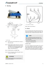
Step 1: Pull out the plug.
Step 2: Take out the safety screw and open the cover.
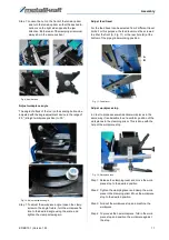
Fig. 6: Adjust the work surface
Step 3: Screw the working surface to the device side with
two Allen screws.
Step 4: Adjust the position of the work surface after loos
-
ening the fixing screws on the side of the unit
and then tighten the screws. The distance of the
work surface to the sanding belt may be max. 2
mm.
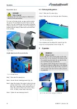
Step 5: After completion of the work on the rear work sur
-
face, the cover must be closed. To do this, fold
down the work surface after loosening the fixing
screws or remove it.
Then close the cover and tighten the fixing
screw.
Fig. 7: Cover on the back of the Machine
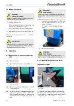
8.2 Pipe grinder on the front of the device
Adjust clamping prism
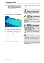
Fig. 8: Prism
The clamping prism has 4 different shots for clamping
different profiles and tubes on the four sides. Depending
on the shape of the workpiece, the most suitable recep
-
tacle can be selected and mounted.
DANGER!
Danger by voltage!
Danger by voltage! Working on the electrical connec
-
tion may only be done by electricians
ATTENTION!
After connecting the plug. you have to check the run
-
ning direction of the engine. Should this be wrong,
you have to change the two phases.
DANGER!
Risk of injury!
Never reach into the gap between the roller and the
housing when the machine is connected to the power
supply!
DANGER!
Risk of injury!
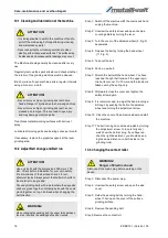
If you do not work at the rear grinding position, the
sanding belt cover must always remain closed!
Summary of Contents for KRBS 101
Page 1: ...KRBS 101 Instruction Manual KRBS 101 KRBS 101 Combined pipe section and belt grinding machine...
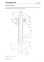
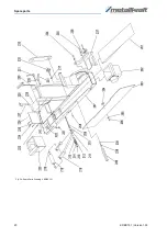
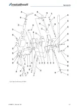
Page 20: ...20 KRBS 101 Version 1 03 Spare parts Fig 24 Spare Parts Drawing 2 KRBS 101...
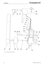
Page 21: ...Spare parts KRBS 101 Version 1 03 21 Fig 25 Spare Parts Drawing 3 KRBS 101...
Page 22: ...22 KRBS 101 Version 1 03 Spare parts Fig 26 Spare Parts Drawing 4 KRBS 101...
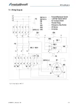
Page 23: ...Wiring Diagram KRBS 101 Version 1 03 23 13 Wiring Diagram Fig 27 Wiring Diagram KRBS 101...
Page 25: ...Notes KRBS 101 Version 1 03 25 15 Notes...
Page 26: ...www metallkraft de...

