12
KRBS 101 | Version 1.03
Operation
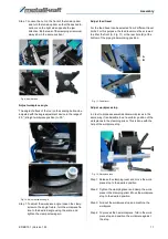
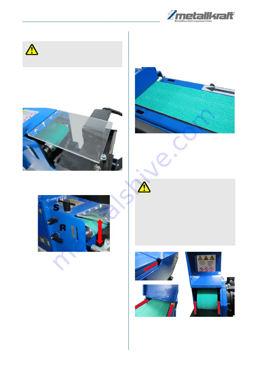
Pipe sander cover
The cover at the pipe grinder working position protects
the operator from workpiece swarf and dust as well as
sparks. The cover must always be mounted and lowered
while the machine is in operation. Due to the transparent
material, the machining process can be well monitored
and controlled.
Fig. 13: Cover
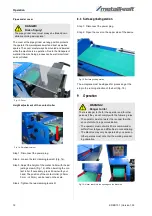
Height adjustment of the contact roller
Fig. 14: Height adjustment
Step 1: Disconnect the power plug.
Step 2: Loosen the two clamping levers R (Fig. 14).
Step 3: Adjust the height of the contact roller with the ad
-
justing screw S (Fig. 14). When lowering the con
-
tact roller, if necessary, press it down with your
hand. The position of the contact roller (-20 mm -
0 mm - +20 mm) can be read on the scale.
Step 4: Tighten the two clamping levers R.
8.3 Surface grinding station
Step 1: Disconnect the power plug.
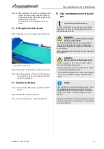
Step 2: Open the cover on the upper side of the device
Fig. 15: Surface grinding station
The workpiece must be stopped for processing at the
stop in the running direction of the belt (Fig. 15).
9
Operation
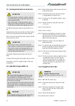
Fig. 16: Never reach into the openings on the Machine
DANGER!
Risk of injury!
The pipe grinder cover must always be folded down
while machining a workpiece!
WARNING!
Danger to life!
There is danger to life for the operator and for other
persons if they do not comply with the following rules.
- The operator must not work if he is under the influ
-
ence of alcohol, drugs or medication.
- The operator must not work if he is overworked or
suffers from fatigue and difficulties in concentrating.
- The Machine may only be operated by one person.
Other persons must not enter the working area dur
-
ing operation.
Summary of Contents for KRBS 101
Page 1: ...KRBS 101 Instruction Manual KRBS 101 KRBS 101 Combined pipe section and belt grinding machine...
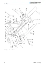
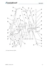
Page 20: ...20 KRBS 101 Version 1 03 Spare parts Fig 24 Spare Parts Drawing 2 KRBS 101...
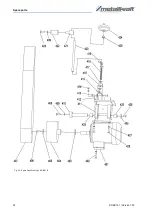
Page 21: ...Spare parts KRBS 101 Version 1 03 21 Fig 25 Spare Parts Drawing 3 KRBS 101...
Page 22: ...22 KRBS 101 Version 1 03 Spare parts Fig 26 Spare Parts Drawing 4 KRBS 101...
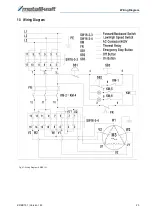
Page 23: ...Wiring Diagram KRBS 101 Version 1 03 23 13 Wiring Diagram Fig 27 Wiring Diagram KRBS 101...
Page 25: ...Notes KRBS 101 Version 1 03 25 15 Notes...
Page 26: ...www metallkraft de...

