20
PRM FH | Version 1.04 | EN
Operation
9.1 Control panel
9.1.1Function assignment of the control elements
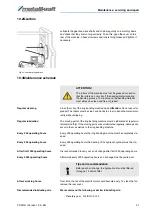
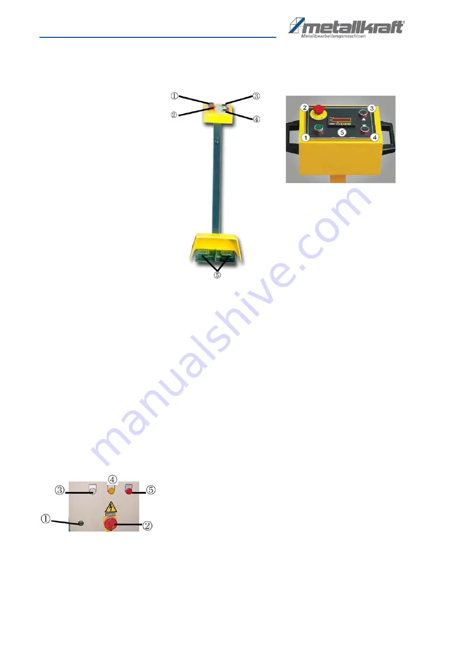
Fig. 12: Control panel, right with digital display (optional)
The control panel (Fig. 12) is provided with the following functions:
1 START button
2 EMERGENCY STOP button
3 Control button:
Move upper roller upwards
4 Control button:
Move upper roller down
5 Pedals
: Right pedal: Rotation of the rollers, movement of the workpiece to
the right.
Left pedal: Rotation of the rollers, workpiece movement to the left.
5 Digital display
(optional, Fig 12, right):
Display and Input of the position of the upper roller.
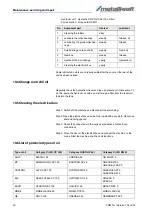
Electric box
1
Electric box lock
2
Main switch
3
Power indicator
4
Indicator „Hydraulic pump on“.
5
Indicator „Thermal motor overload“
Fig. 13: Electric box with indicators
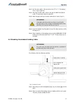
Set the ring bending machine ready
for operation
With the following steps, the ring bending machine is set to operating state.

