background image

8

RBM  E | Version 1.07

Safety

2.5 General safety regulations

Please note the following: 

- Use the guards and secure them securely. Never work without protecti

-

ons and get them working.

- Keep the machine and its working environment always clean. Ensure 

adequate lighting.

- The machine may not be modified in its design and may not be used for 

purposes other than those foreseen by the manufacturer.

- Never work under the influence of concentration-disturbing illnesses, fati

-

gue, drugs, alcohol or medicines.

- Keep children and people unfamiliar with the machine away from their 

work environment.

- Do not pull on the mains lead to pull the plug out of the socket. Protect 

the cable from heat, oil and sharp edges.

- Disruptions that affect safety are eliminated immediately.

- Protect the machine against moisture (danger of short circuit)

- Before using the machine, make sure that no parts are damaged. Dama

-

ged parts must be replaced immediately to avoid any danger.

- Do not overload the machine! You work better and safer in the specified 

performance range.

- Only use original spare parts and accessories to avoid possible dangers 

and accident risks.

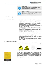
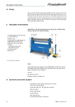
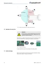
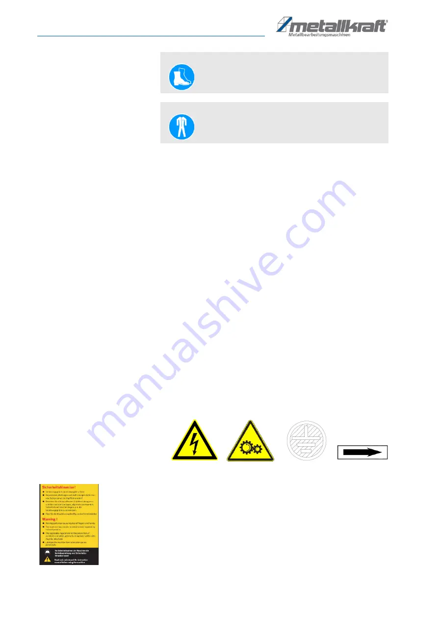
2.6 Safety lables on the machine

Safety markings and instructions are attached to the bending machine (Fig. 1, 
2), which must be observed and followed.  

Fig. 1: Safety labels

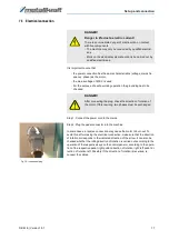
The safety markings and instructions attached to the bender must not be re

-

moved. Damaged or missing safety markings can lead to malfunctions, perso

-

nal injury and property damage. They are to be replaced immediately.If the 
safety markings and instructions are not immediately recognizable and com

-

prehensible, the round bending machine must be taken out of operation until 
new safety markings have been made.

Fig. 2: Safety labels
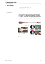
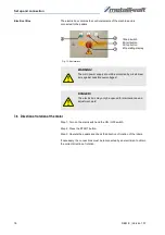
Safety boots 

Safety boots protect the feet from being crushed, falling 
parts and slipping over on slippery ground. 

Protective clothes 

Protective clothes are made of a tightly fitted fabric without 
the protruding parts of low tear strength. 

1

2

 3

4

Summary of Contents for RBM 1050-30 E

Page 1: ...RBM 1270 25 E Instruction Manual RBM 1050 30 E RBM E SERIES Plate rolling machines RBM 1270 25 E RBM 1550 20 E RBM 2050 15 E...

Page 2: ...kraft de Indications regarding the operating instructions Original instructions Edition 14 05 2019 Version 1 07 Language English Author ES MS Indications regarding the copyright Copyright 2019 St rmer...

Page 3: ...12 6 1 Specification and standard equipment 12 6 2 Optional equipment 13 6 3 Safety switch 13 7 Set up and connection 14 7 1 Set up 14 7 2 Danger zones 15 7 3 Assembly of the safety line 16 7 4 Lubric...

Page 4: ...ed without the written approval of St rmer GmbH For the protection of our products we shall register trademark patent and de sign rights as this is possible in individual cases We strongly oppose any...

Page 5: ...ting personnel as well as for safe and fault free operation Other task based safety notes are included in the paragraphs of the individual phases of life 2 1 Symbol explanation Safety instructions The...

Page 6: ...t these in the form of operating instructions for the operation of the machine The operator must check during the entire period of use of the machine whether the operating instructions he has prepared...

Page 7: ...personnel Due to their professional training knowledge and experience as well as their knowledge of relevant regulations the specialist staff is able to perform the as signed tasks and to recognise an...

Page 8: ...ged parts must be replaced immediately to avoid any danger Do not overload the machine You work better and safer in the specified performance range Only use original spare parts and accessories to avo...

Page 9: ...of the safety regulations or the operating instructions exclude liability of the manufacturer for resulting da mage to persons or objects and cause the warranty to expire 3 1 Misue If the intended us...

Page 10: ...please report this immediately to the carrier or dealer Transport RBM 1050 30 E RBM 1270 25 E RBM 1550 20 E RBM 2050 15 E Bending width 1050 mm 1270 mm 1550 mm 2050 mm Max sheet thickness 3 mm 2 5 mm...

Page 11: ...ould be taken to a materials recycling depot to be disposed of The delivery packaging is made of cardboard so please dispose carefully by having it chopped up and given to the recycling collection The...

Page 12: ...sign Fig 6 Description of the RBM E Pedal The standard pedal is equipped with an EMERGENCY STOP button which immediately interrupts all machine movements when disconnected from the power connection un...

Page 13: ...rsonnel the machine is equipped with a safety switch and a safety line When the leash is operated the ring shown below is pulled like the EMERGENCY STOP stopping all machine activities To restart pull...

Page 14: ...ial transport as well as for adjustment and maintenance work The site must have good lighting Space requirement Fig 8 Space requirement of the machine The measure of the space requirement on the right...

Page 15: ...ar or other gears Ano ther area of danger that must be carefully observed during the machining process is the turning range of the rollers The danger area shown below must be kept clear during operati...

Page 16: ...e machine by the customer as shown below Fig 11 Assembly of the safety line It is essential that the leash is firmly attached to the safety switch 7 4 Lubricate bearings Before using the machine for t...

Page 17: ...tion of the arrow It can also be checked whether the rolling direction of rotation is carried out according to the operation of the respective keys on the control panel or according to the opera tion...

Page 18: ...ch Step 2 Press the START button Step 3 Operate the pedals and check the direction of rotation of the rollers If necessary the connections must be reconnected by an electrician to obtain the correct d...

Page 19: ...t by qualified persons Keep inadequately qualified persons out of the work area WARNING Risk of crushing The upper limbs must be kept away from the machine during insertion and during machining of the...

Page 20: ...eral passes are required Narrow arcs and full radii always require multiple passes NOTE It is important to thoroughly clean the rollers to avoid pos sible slippage of the profile due to grease residue...

Page 21: ...elism of rollers Step 3 Turn on the main switch The operating display lights up Step 4 Press the START button Step 5 Press the rollers with the pedals Step 6 Perform Bending Step 7 Stop the rollers af...

Page 22: ...e Remove dirt and oil from the material The material ends must be free of chips and burnt residues Burnt material is harder at the points of separation than in the remaining area The material has to b...

Page 23: ...the material are bent to the same radius as the final radius This will give the best results at full radii eg making tubes or for operations where no flat ends are desired 8 2 4 Bending NOTE The mate...

Page 24: ...ing Conical bending is more difficult than normal bending The machine perfor mance is reduced by 30 to 50 the conical bending capacity decreases by about 25 The material thickness must be reduced acco...

Page 25: ...al bending as follows Move the lower roller and the rear roller to the lowest position Fig 17 Conical bending tool left and couplings right Release the fastening bolts of the couplings Pull off coupli...

Page 26: ...ep 1 Use the handwheels to bring the back roll and bottom roll parallel to the top roll Step 2 Connect couplings Step 3 Check the parallelism of the rollers with a gauge 8 2 7 Removal of the workpiece...

Page 27: ...ice 8 2 8 Counterweight At the top of the housing of the top roller is the screw for the balance weight It prevents the top roller from tilting too far when extending Turn clockwise CW for more counte...

Page 28: ...a danger to life when in contact with live compo nents Always unplug the appliance before cleaning and main tenance Connections and repairs of the electrical equipment may only be carried out by a qu...

Page 29: ...east once a month or more often for a period of more than eight hours daily Some of these locati ons are inside the machine and can only be accessed after removing the cover Fig 24 Parts to be lubrica...

Page 30: ...anagement If necessary the help of a specialized waste management company can be used for the treatment 10 3 Disposal of lubricants Remove any leaking used or excessive grease at the lubricating point...

Page 31: ...e on the type plate fixed to the Machine Example The top roller for the RBM 2050 15 E round bending machine must be or dered This is indicated in the spare parts drawing with the item number 5 Type of...

Page 32: ...2 Spare parts drawing In case of service the following drawing shall help to identify the necessary spare parts If necessary send a copy of the parts drawing with the marked components to your authori...

Page 33: ...Electrical schematic RBM E Version 1 07 33 12 Electrical schematic Fig 26 Electrical schematic...

Page 34: ...gn and construction as well as the version that we have put into circulation with the relevant fundamental health and safety requirements of subsequent EC guidelines Relevant EU directives 2014 30 EU...

Page 35: ...Notes RBM E Version 1 07 35 14 Notes...

Page 36: ...www metallkraft de...

Reviews: