background image

Description of the Device

RBM 305 | Version 2.02

7

6

Description of the Device

Illustrations in this operating manual serve the gene

-

ral understanding and may deviate from the actual 
design.

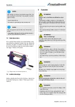
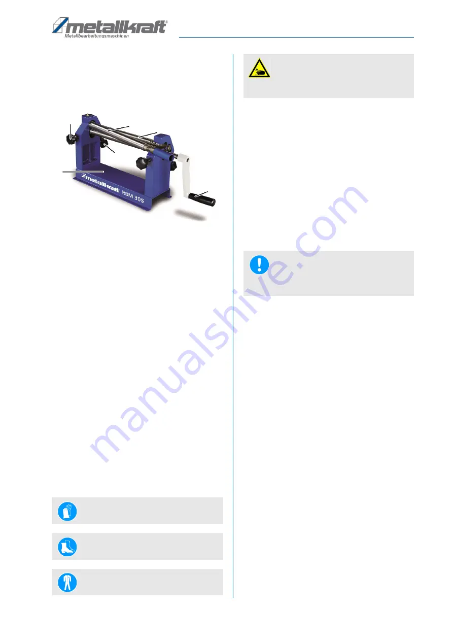
Fig. 3: Description of the RBM 305

1 Adjusting wheel guide roller (plate thickness)
2 Guide roller
3 Guide roller
4 Adjusting wheel guide roller (radius)
5 Winch
6 Machine frame

6.1 Scope of delivery

The scope of delivery of the machine includes:

- Asymmetrical 3-roller system with swing-out top 
  roller

- Rolls of steel

- Conical-bender

- operating manual

Optional accessories:

- Substructure   Item number: 3780113

7

Assembly

7.1 Setting up the machine

To achieve good functionality and long life of the plate 
rolling machine, the site should meet the following crite

-

ria:

- The substrate must be level, firm and vibration-

free.

- The installation or work area must be dry and well 

ventilated.

- Do not operate machines that cause dust and 

chips near by.

- There must be sufficient space for the operating 

personnel, for material transport as well as for ad

-

justment and maintenance work.

- The site must have good lighting.

Space Requirement

The measure of the space requirement on the right side 
of the machine should be slightly larger than a roll length 
and allow easy material removal.

The amount of space required in front of and behind the 
machine should be calculated so that the operator can 
easily feed the material and remove it from the machine. 

Step 1: Place the machine on a level and stable surface, 

such as a workbench.

Step 2: The round bending machine is to be mounted on 

the base and aligned horizontally with a spirit 
level. Pay attention to the space required.

Step 3: Place the round bending machine on the base 

and mark the 4 specified holes.

Step 4: Take the bender from the pad and pierce the 

markers. The holes should be 6.5mm.

Step 5: Attach the Bending Machine to the base and use 

four screws (M6) that are about 20mm longer 
than the thickness of their backing. Use 8 was

-

hers and 4 nuts.

Wearing safety gloves!

Wear safety shoes!

Wear protective clothing!

2

3

5

4

1

6

ATTENTION!

Crushing!

The Plate rolling Machine can tilt when setting up 
and cause injury.

NOTE!

-  The plate rolling machine is already pre-assembled 

on delivery.

Summary of Contents for RBM 305

Page 1: ...Operating Instructions Plate rolling machine RBM 305 RBM 305 RBM 305...

Page 2: ...3 1 1 Copyright 3 1 2 Customer service 3 1 3 Limitation of liability 3 2 Safety 3 2 1 Symbol explanation 3 2 2 Requirements to staff 4 2 3 Personal protective equipment 4 2 4 General safety regulatio...

Page 3: ...ce and knowledge gained from using the application which then could be shared and be valuable to develop our products even further 1 3 Limitation of liability All information and notes in these operat...

Page 4: ...in works may only be performed by specialist per sonnel of the manufacturer Other personnel is not au thorized to perform these works Please contact our cus tomer service for the execution of all aris...

Page 5: ...ne has various warning labels and safety markings that must be observed and followed The safety markings attached to the plate rolling ma chine must not be removed Damaged or missing safety markings c...

Page 6: ...e carrier or dealer 5 2 Packaging All used packaging materials and packaging aids are re cyclable and should be taken to a materials recycling de pot to be disposed of The delivery packaging is made o...

Page 7: ...ort as well as for ad justment and maintenance work The site must have good lighting Space Requirement The measure of the space requirement on the right side of the machine should be slightly larger t...

Page 8: ...er sons Insufficiently qualified persons can not assess the risks involved in handling the bending machine and expose themselves and others to the risk of serious injury All work should only be carrie...

Page 9: ...the guide Fig 5 Locking uper roll 8 1 Work flow Step 1 Before starting the machine check the locking of the top roller Step 2 Check the parallelism of the rollers with a gauge and a spirit level Fig...

Page 10: ...ding and conical bending must be carried out ex tremely carefully It should be noted that a small radius is made by repeating the bending process several times Once too much bent this step can not be...

Page 11: ...ensions Fig 13 Calculation of the workpiece dimensions Bending process Step 1 Before conical bending the sheet must be pre bent at the ends with parallel rolls Step 2 Then the machine has to be prepar...

Page 12: ...e correct notch and turn the handle to shape it The remaining procedures and adjustments are identical to those of bending a sheet Fig 17 Bending of wires 9 Care maintenance and repair WARNING Never c...

Page 13: ...tic parts or painted surfaces A surface release and consequential da mage may occur DANGER The rollers must not be lubricated or oiled You would allow slipping of the material and thus trigger no ben...

Page 14: ...e following basic information for requests or orders of spare parts Type of device Item No Position No Year of construction Quantity Required mode of dispatch mail freight sea air express Address of d...

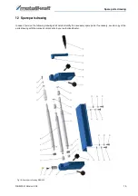
Page 15: ...2 Spare parts drawing In case of service the following drawing shall help to identify the necessary spare parts If necessary send a copy of the parts drawing with the marked components to your authori...

Page 16: ...mity according to Machinery Directive 2006 42 EC Annex 1 does not require this machine In the event of a modification of the machine not agreed with us this declaration shall lose its validity Product...

Page 17: ...Notes RBM 305 Version 2 02 17 14 Notes...

Page 18: ...www metallkraft de...

Reviews: