


10
UB 10 | Version 2.01
Work and operation
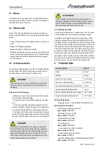
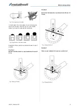
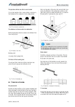
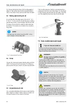
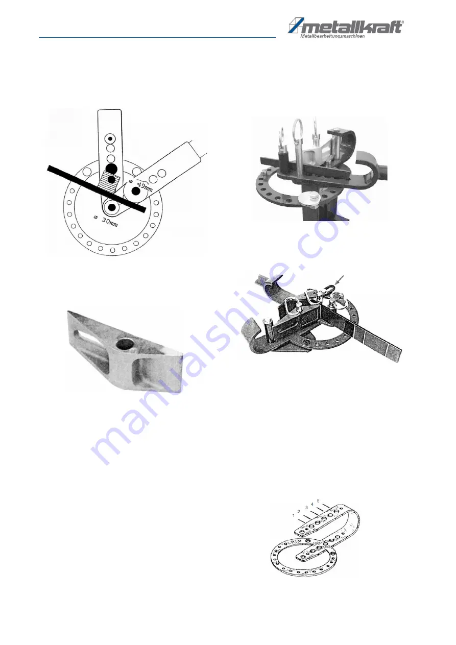
Position 4
Rectangular or round steel of 16 mm: Use Ø 30 mm
bending roller
Fig. 10: Example Position 4
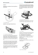
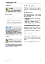
Application of right-angle bending accessory
Fig. 11: Application of the bending accessory
If you want to bend a right angle, mark the location of the
sheet with chalk. When inserting the material into the
bending machine, make sure that the marked area is still
partially visible. The bending edge of the right-angle ben
-
ding accessory covers the other side of the marked loca
-
tion.
If two right angles are to be bent on the same flat mate
-
rial (eg 5 x 25 mm), the marked points must be separa
-
ted by 3 mm more than the required inner dimension. If
the material thickness is different, the corresponding
bending allowances must be taken into account
If very precise work is needed, first bend a specimen be
-
fore bending a large amount. So you can find out if you
need to move the spot or if you need to lengthen or shor
-
ten the material.
This instruction manual specifies the bending measure,
but if you are unsure about the dimensions, it is better to
use a narrower material than the required thick material,
which would be more expensive. If you are sure about
the bending and bending degree, make a note of it for
further use.
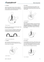
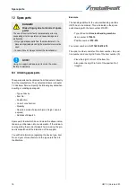
Fig. 12: Application of the bending accessory
The adjustable stop is used for equal curvatures. Make
sure that the screw is tight and that the stopper is tight.
Fig. 13: Chalk mark
This image shows the exact position of the chalk mark against
the bending edge of the right-angle bending accessory.
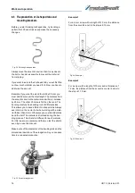
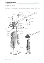
8.2 The production of U-shaped tabs
Preparing the material - The length of the material for U-
shaped tabs must be cut according to the size of the
bending element.
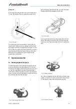
The holes in the carrier plate
The number of the hole in which the ex-centric counter
-
holder is placed.
Fig. 14: Holes of the carrier plate


