8
UB 10 | Version 2.01
Work and operation
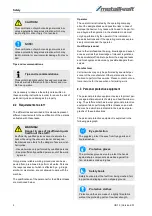
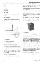
1 screw
2 screw
3 Nut
4 spacer tube
5 spacer ring
7.1 Set up
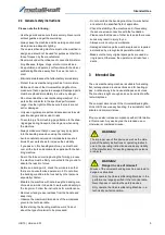
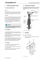
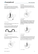
Mount the machine firmly on the ground at a suitable
location.
Note the following:
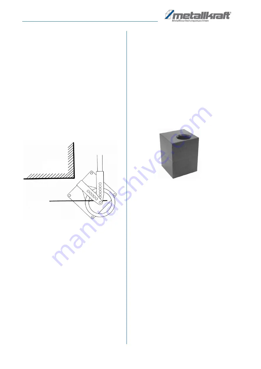
• Make sure you have enough space around the ma
-
chine (see Fig. 3).
• Make sure that the bending machine is firmly screwed
to the floor.
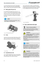
Fig. 3: Set up example
8
Work and operation
Information about the use of the machine
• Do not bend other steels than standard structural steel.
(8 x 50 mm and round steel up to Ø16 mm, rectangular
steel up to a size of 14 x 14 mm and heating pipes up to
a size of G3 / 4˝!
• Do not bend materials thicker than 6 mm around the
center pin. Always use the Ø24 mm rollers to prevent the
bolt from bending.
• Do not use additional lever extension.
• Do not use the right-angle bending accessory to bend
wooden blocks.
• When using the right angle bend accessory, bend only
standard steel up to 6 x 50 mm or 7 x 30 mm.
• Keep the work area around the machine clean to avoid
unnecessary accidents.
• Preventing the bending roller from dropping suddenly
could cause serious injury.
• When shearing, edging and bending, you can mount a
rip fence. To do this, screw the guide pins of the rip fence
to the frame.
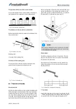
8.1 Application of the eccentric counter-holder
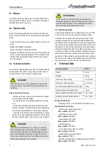
This counterholder in the bending arm ensures that the
material is firmly clamped during the bending process.
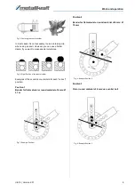
Fig. 4: Counter-holder
The eccentric anvil offers four positions. Always use the
proper position to bring the anvil as close as possible to
the center pin or roller, but make sure that a small gap is
left for the material.
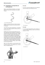
To reach two of the four positions, the anvil must rotate
from side to side. If the hole is to the left of the center, the
backstop will slip and thus the material will. If you are
using a large bending roller, insert the counterholder and
stop into the corresponding hole so that the material is
firmly attached. Place the anvil as close to the central
bolt or to the bending roller as possible and turn the anvil
into one of the four positions. You can adjust the stop on
the support plate by one hole forward or backward to
achieve the required clearance.
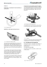
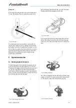
Too large a distance between the central bolt or the ben
-
ding roller and the stop causes the slipping of the mate
-
rial and thus an inaccurate bending radius.
If a very accurate bend radius is desired, it is prudent to
secure the material with a retainer clip against the anvil
to prevent the material from slipping.
Wall


