19
OPERATION MANUAL
4.3 CONTROLS
Before operating the machine it is important to know where the
controls are and what each item does.
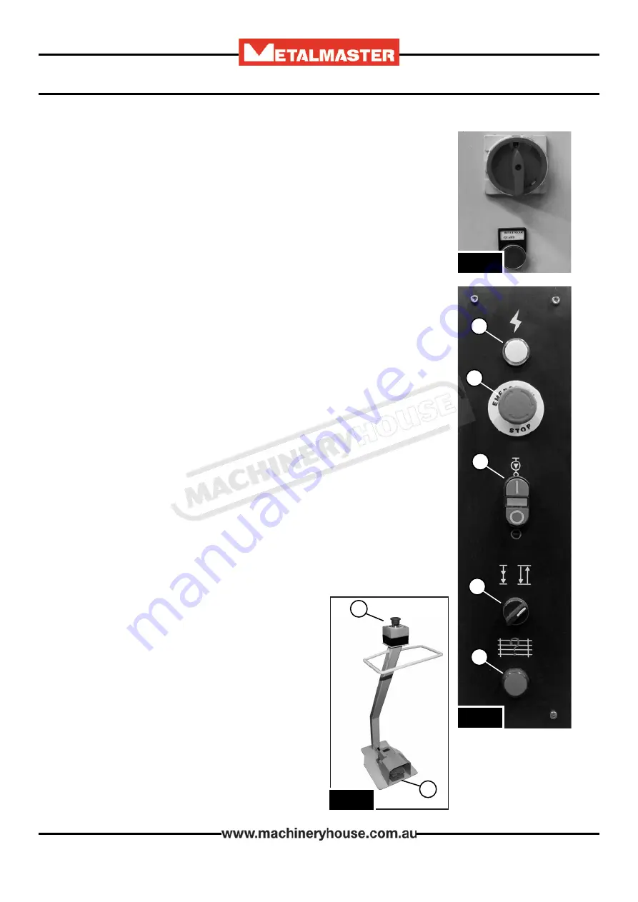
The controls for the machine are found in three places.
1. The back of the electrical cabinet
2. The control panel situated on the right hand side of the machine
on the front of the electrical cabinet.
3. The mobile foot pedal.
Below are the explanation of each control.
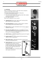
A. Isolating Switch.
Main power supply switch mounted on the
back of the electrical cabinet. (Fig.4.4)
B. Safety Reset Button.
This button resets the safety circuit after
the rear safety beam has been broken. (Fig.4.4)
C. Power Lamp.
This light is illuminated when the power supply is
switched on. (Fig.4.5)
D. Emergency Stop Buttons (2).
When pressed disconnects the
power to the machine. The button needs to be twisted to release
and reset the circuity (Fig.4.5) (Fig.4.6)
E. ON/OFF Button.
Switches the Hydraulic pump ON of OFF (Fig.4.5)
F. Function Switch.
This switch switches the function between
“INCH” or “CYCLE” mode (Fig.4.5)
G. Rear Sensor Lamp.
Is illuminated when the rear safety guard
circuit has been tripped (Fig.4.5)
D
E
F
G
A
B
C
H
D
H. Operating Pedal.
When pressed, activates
the guillotine when either “Inching” or
Cycling” mode has been selected. (Fig.4.6)
If in the “INCHING” mode, the top blade can
be moved and stopped by pressing and
releasing the pedal.
If in the “CYCLING” mode, pressing the pedal
will complete one full cycle.
F
ig
. 4.6
F
ig
.4.4
F
ig
. 4.5
22/07/2019
Instructions Manual for SG-420 (S535)
19


