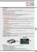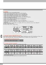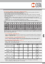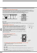
42
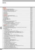
INDEX
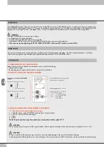
INTENDED USE
PAGE 44
TARGET GROUP
PAGE 44
1. INSTALLATION
PAGE 44
1.1 GENERAL INSTRUCTIONS FOR INSTALLATION
PAGE 44
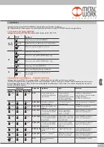
1.2 ELECTRICAL CONNECTION AND DISPLAY ELEMENTS
PAGE 44
1.3 ELECTRICAL CONNECTIONS: PIN ASSIGNMENT OF CONNECTOR
PAGE 44
1.3.1 M8 connector for node and output power supply
PAGE 44
1.3.2 M12 connector for connection to the POWERLINK network
PAGE 45
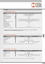
1.4 POWER SUPPLY
PAGE 45
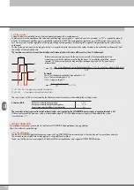
1.4.1 Supply voltage
PAGE 45
1.4.2 Input current
PAGE 46
1.5 MAINS CONNECTION
PAGE 46
1.5.1 Use of Switches
PAGE 46
2. COMMISSIONING
PAGE 47
2.1 CONNECTIONS TO THE EB 80 POWERLINK SYSTEM
PAGE 47
2.2 INSTALLATION OF THE EB 80 SYSTEM IN A POWERLINK NETWORK
PAGE 47
2.2.1 XDD configuration file
PAGE 47
2.2.2 Static mapping
PAGE 47
2.2.3 Dynamic mapping
PAGE 47
2.2.4 Dynamic mapping – bit offset
PAGE 47
2.2.5 Address assignment
PAGE 47
2.3 EB 80 SYSTEM CONFIGURATION
PAGE 47
2.4 ADDRESSING
PAGE 48
2.5 CONFIGURING THE EB 80 SYSTEM IN POWERLINK NETWORK
PAGE 48
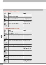
2.5.1 Assigning data bits to solenoid valve base outputs
PAGE 48
2.5.2 Examples of solenoid pilot output addresses
PAGE 48
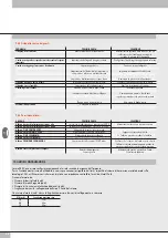
2.5.3 Unit parameter configuration - System Parameters – FailSafeOutput_I5F01_S01
PAGE 49
2.5.3.1 Start-up parameters - SystemStart_I5F01_S02
PAGE 49
2.5.3.2 Analogue input display - VisualizationOfAnalogueValues_I5F01_S03
PAGE 49
2.5.3.3 Analogue data format - AnalogueInputDataFormat_I5F01_S04
PAGE 49
3. ACCESSORIES
PAGE 50
3.1 INTERMEDIATE MODULE - M, WITH ADDITIONAL POWER SUPPLY
PAGE 50
3.2 ADDITIONAL ELECTRICAL CONNECTION - E0AD
PAGE 50
3.2.1 Electrical connections and signal display elements
PAGE 50
3.2.1.1 Electrical connections: pin assignment of M8 connector for Additional Electrical Connection power supply
PAGE 50
3.2.2 Addressing the Additional Electrical Connection - E0AD
PAGE 51
3.3 SIGNAL MODULES - S
PAGE 51
3.3.1 Digital Input module
PAGE 51
3.3.1.1 Type of inputs and power supply
PAGE 51
3.3.1.2 Electrical connections
PAGE 51
3.3.1.3 Polarity - PolarityDI8_x_I5F20_Sxx - PolarityDI16_x_I5F20_Sxx
PAGE 51
3.3.1.4 Activation State - ActivationStateDI8_x_I5F21_Sxx- ActivationStateDI16_x_I5F71_Sxx
PAGE 52
3.3.1.5 Signal persistence - SignalExtensionDI8x_x_I5F22_Sxx - SignalExtensionDI16x_x_I5F72_Sxx
PAGE 52
3.3.1.6 Input filter - DebounceTimeDI8x_x_xI5F23_Sxx - DebounceTimeDI16x_x_xI5F73_Sxx
PAGE 52
3.3.2 Digital Output module
PAGE 52
3.3.2.1 Type of output and power supply
PAGE 52
3.3.2.2 Electrical connections
PAGE 52
3.3.2.3 Polarity - PolarityDO8_x_I5F30_Sxx - PolarityDO16_x_I5F80_Sxx
PAGE 52
3.3.2.4 Operating state - ActivationStateDO8_x_I5F31_Sxx - ActivationStateD16_x_I5F81_Sxx
PAGE 53
3.3.2.5 Fail safe outputs - FailSafeOutputDO8x_x_I5F32_Sxx - FailSafeOutputDO16_x_I5F82_Sxx
PAGE 53
3.3.2.6 Faults and alarms
PAGE 53
3.3.3 Digital 6-Output M8 electrical power supply
PAGE 53
3.3.3.1 Auxiliary power supply
PAGE 53
3.3.4 Analogue 4-Input M8 Module
PAGE 53
3.3.4.1 Electrical connections: Pin assignment of M8 connector
PAGE 53
3.3.4.2 Signal range - Signal_RangeAI_x_I5F50_Sxx
PAGE 54
3.3.4.3 Filtering the value measuredo - FilterMeasuredValueAI_x_I5F51_Sxx
PAGE 54
3.3.4.4 User full scale - UserFullScaleAI_x_I5F52_Sxx
PAGE 54
3.3.4.5 Connection of sensors
PAGE 54
3.3.5 Analogue 4-Output M8 Module
PAGE 54
3.3.5.1 Electrical connections: Pin assignment of M8 connector
PAGE 54
3.3.5.2 Signal Range - Signal_RangeAO_x_I5F60_Sxx
PAGE 55
3.3.5.3 User full scale - UserFullScaleAO_x_I5F61_Sxx
PAGE 55
3.3.5.4 Minimum monitor - MonitorLowestValueAO_x_I5F62_Sxx
PAGE 55
3.3.5.5 Maximum monitor - MonitorHighestValueAO_x_I5F63_Sxx
PAGE 55
3.3.5.6 Minimum value - LowestValueScaleAO_x_I5F64_Sxx / HighestValueScaleAO_x_I5F65_Sxx
PAGE 55
3.3.5.7 Fail Safe Output - FailSafeOutputAO_x_I5F66_Sxx
PAGE 55
3.3.5.8 Fault mode value - FaultModeValueAO_x_I5F67
PAGE 55
3.3.6 M8 analogue 4-input module for temperature measurement
PAGE 56
3.3.6.1 Electrical connections of temperature sensors (Pt and Ni series)
PAGE 56
3.3.6.2 Electrical thermocouple connections
PAGE 56
Summary of Contents for EB 80 ETHERNET POWERLINK
Page 1: ...MANUALE D USO USER MANUAL ...

