45
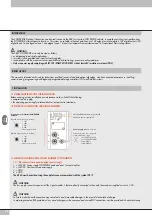
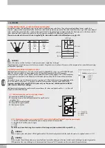
1.3.2 M12 connector for connection to the POWERLINK network
1 = TD+
2 = RD+
3 = TD-
4 = RD-
Metal ring nut = Shield
The network connectors are the M12 D-coded type, in accordance with POWERLINK specifications. Pre-wired Industrial Ethernet cables can be
used to prevent any malfunction due to faulty wiring or, as an alternative, recyclable Industrial Ethernet 4-pin M12 metallic male connectors can
also be used. Connection to Master may require an RJ45-M12 male D-coded connecting cable to be provided with the following Metal Work
catalogue codes:
• 0240005050 - RJ45 4-pin connector to IEC 60 603-7;
• 0240005093 / 095 /100100100 - Straight M12 D-coded connector for bus with cable.
WARNING
For correct communication, only use Industrial Ethernet cables, cat. 5 / Class D 100MHz of the type shown in the Metal Work catalogue.
Incorrect installation can cause transmission errors and lead to malfunction of the devices.
The most frequent causes of data transmission faults are:
• wrong connection of shield or leads;
• cables too long or unsuitable;
• Network components unsuitable for branching.
1.4 POWER SUPPLY
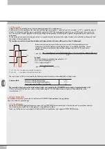
An M8 4-pin female connector is used for the power supply. The auxiliary power supply of the valves is separate from that of the fieldbus, which
means that the valves can be powered off while the bus line remains live. The absence of auxiliary power is indicated by the flashing of the Led Power
light and simultaneous flashing of all the solenoid valve Led lights. The fault is relayed to the Master, which provides for adequate management of the
alert.
WARNING
Power off the system before plugging or unplugging the connector (risk of functional damage).
Use fully assembled valve units only.
Only use power packs complying with IEC 742/EN60742/VDE0551 with at least 4kV insulation resistance (PELV).
1.4.1 Supply voltage
The system provides a wide voltage range, from 12VDC -10% to 24VDC +30% (min 10.8, max 31.2).
CAUTION!
Voltage greater than 32VDC irrevocably damages the system.
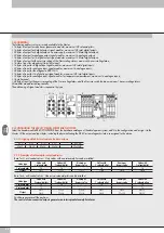
SYSTEM VOLTAGE DROP
Voltage drop depends on the input maximum current drawn by the system and the length of the cable for connection to the system.
In a 24VDC-powered system, with cable lengths up to 20 m, voltage drops do not need to be taken into account.
In a 12VDC-powered system, there must be enough voltage to ensure correct operation. It is necessary to take into account any voltage drops due
to the number of active solenoid valves, the number of valves controlled simultaneously and the cable length.
The actual voltage supplied to the solenoid pilots must be at least 10.8VDC.
A synthesis of the verification algorithm is shown here below.
Maximum current: I max [A] = (no. of solenoid pilots controlled simultaneously x 3.2) + (no. of active solenoid valves x 0.3)
VDC
Voltage drop: with a M8 cable: ΔV = I max [A] x Rs [0.067Ω/m] x 2L [m]
Where Rs is the cable resistance and L its length.
The voltage at the cable inlet, Vin must be at least 10.8VDC + ΔV
Example:
12VDC supply voltage, 5 m cable, 3 pilots activate while other 10 are already active:
I max = (3 x 3.2) + (10 x 0.3) = 1.05 A
12
ΔV = (1.05 x 0.067) x (2 x 5) = 0.70VDC
This means that at the power supply voltage greater than or equal to 10.8 + 0.7 = 11.5VDC is required.
Vin =12VDC > 11.5
→
OK
Summary of Contents for EB 80 ETHERNET POWERLINK
Page 1: ...MANUALE D USO USER MANUAL ...


